Continue to Site

Welcome to our site!

Electro Tech is an online community (with over 170,000 members) who enjoy talking about and building electronic circuits, projects and gadgets. To participate you need to register. Registration is free. Click here to register now.

  • Welcome to our site! Electro Tech is an online community (with over 170,000 members) who enjoy talking about and building electronic circuits, projects and gadgets. To participate you need to register. Registration is free. Click here to register now.

Voltage polarity indicator help

Status
Not open for further replies.

skithat2004

New Member
Hello, i have to design a citcuit which will light a colred LED if the voltage is less than 5v and another LED would light if the voltage is more than 5v. i would like some ideas or tips on how to construct such a circuit and what type of components is need. if you could pass on any helpful websites that would be great.

thanks a lot
 
Use the 5 volt rail as a reference,
and it becomes easy.

John :)
 

Attachments

  • Logic_339.jpg
    Logic_339.jpg
    7 KB · Views: 1,671
ok, how would i use the opamp so that the LED knows how much voltage its getting? this is the first time ive had to design a circuit and i really appreciate all the advice.
 
Using an Op-amp here would suggest a comparitor circuit, as mentioned above by Pike.

check here for an op-amp tutorial which describes a comparator.


here
**broken link removed**

This should give you a good start! Good luck!
 
Ok, i think i understand the concept of how a comparator works, but i'm still having trouble applying it to the circuit i need. how do i make it so that it responds to the 5v cut off range (green led on when above 5V, red on when below).

ive heard that i only need one op-amp to do this, but i still need to figure out what kind of resistors i need and how to connect the LED's to the op-amp. any advice would be greatly appreciated, i'll try to look around for more info as well

thanks
 
Hey thanks for the suggestion. i've done my best to figure this all out and i think i've found a good design. i wasn't too sure about what the value of my resistor should be though or about the positive or negative power supply's

sorry for the crude drawing
 

Attachments

  • opamp.JPG
    opamp.JPG
    7.1 KB · Views: 1,473
This one has two disadvantages.

1. there is no hystersis. So if the input voltage is close to 5 Volt, neither of the LEDs will glow. However you can add hystersis to your circuit by providing a feedback resistor from the output to the + input and series resistors as in my circuit. If you use the same resistor values, you will have about 60 mV of hystersis.

2. you need two supply voltages.

However, it has the advantage that there will be less current required since it does not have the 2 resistors in series across the supply that mine does.

As for your question about the about the positive or negative power supply's, I don't know which IC you intend to use, so I don't know what common mode range it has. In general, you would need supply voltages of at least 8 Volt.

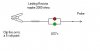
If you make the resistor in series with the LEDs 1k, you will have a LED current of about 6 mA for supply voltages of +/- 8 Volt. If you want the LEDs brighter or dimmer, change the resistor to another value.

You should check the data sheet of the IC you use to ensure that it can source the LED current.
 
Appears to be a good app for a comparator IC such as a LM339, heres a link to some info.

**broken link removed**
 
Yes but, unlike the op amps, comparitors have open collector outputs. So if the LM311 is used, 2 resistors are necessary to make 2 LEDs work.

If the LM339 is used, 3 resistors will be necessary since the emitter of the output transistor is connected to the negative supply pin.

Len
 
wow, ok im pretty sure the circuit i posted up before works. only problem is im having a lot of trouble trying to get it made correctly on a breadboard. if anyone knows how to put such an opamp on a breadboard correctly, your advice would be so great. the way i set up up, i have the opamp staddling the break in the middle of the breadboard. im sure i have a wire out of place somewhere so that all the connections aren't being made right, if anyone can help me correct this it would be awesome


thank you
 
Yes, the circuit you posted will work, but my point that I posted about hystersis is still valid - the LEDs will be dark when the voltage on the + and - inputs is equal.

You did not show bypass capacitors across the supply pins. I normally use a 100 nF from the + supply to gnd and another from the - supply to gnd.

Breadboarding Op Amp circuits is usually not difficult.

But without seeing what you have done, we can only guess and mention generalities.

Does the Op Amp have internal compensation?

Is the Op Amp a FET input one? If so you have to be careful about electrostatic damage. Have you tried another IC?

Have you measured the voltages at each pin of the IC? This usually shows what the problem is assuming the IC is healthy.

Len
 
hey thank everyone for their help with my project and all the links and advice. after must stress, i was able to get my circuit working and actually managed to get 12/10 pts for my report and presentation
once again thanks to everyone for their help, i really appreciate it
 
Status
Not open for further replies.

Latest threads

Back
Top