Continue to Site

Welcome to our site!

Electro Tech is an online community (with over 170,000 members) who enjoy talking about and building electronic circuits, projects and gadgets. To participate you need to register. Registration is free. Click here to register now.

  • Welcome to our site! Electro Tech is an online community (with over 170,000 members) who enjoy talking about and building electronic circuits, projects and gadgets. To participate you need to register. Registration is free. Click here to register now.

Voltage follower enigma

Status
Not open for further replies.

Onda24

New Member
Hi at all! This is my fist message.

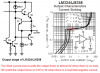
I'm testing a "not inverting voltage follower" with LM358 opamp:
"Vin-" short whit "Vout"
"Vss+" = 12V
"Vss-"= 0V (Single supply)
"Vin+" = [0; 5] V
The load is a R0 = 22Kohm connected toward 5 V (i.e. not toward 0V).

The problem is that when input "Vin+" go under 0.6 V, "Vout" remain to 0.6 and it don't follow the input! What happen when 0V < Vin+ < 0.6V ??
I try the circuit 1)without load and 2) with R0 toward 0V and they work fine even in 0V < Vin+ < 0.6V range.
I think that specifics about "input common-mode" and "output current" are respected.

There is someone that can help me??
 
Hi,

The LM358 really needs a load to 0v not to Vcc to work properly. That's sounds like what you are seeing too.
You have to load it to ground.
 
Thanks MrAl, but I would undestand better the problem, the LM358 datasheet say that this (like almost all) opamp can source but also sink current from out,
so I don't undestand why I don't put load to 5V?...
I can not change the load caracteristics, it is the internal contrast circuit of a 16x2 LCD display. The follower is the interface between DAC and LCD.
 
Last edited:
Two things:

1) You need a rail to rail OP-amp or a dual supply. Think, the output of this amp probably is a transistor in push-pull, thus one diode drop will be there not matter what. Look at the output specs relative to Vss/Vdd and check whether the OP amp can operate off a single supply. The LM324 (https://www.electro-tech-online.com/custompdfs/2011/12/LM124.pdf), is odd because the low end minimum is about 5-20 mV and the max at the high end is Vss-1.2V. There are better OP amps.

2) Always make sure that there is some sort of resistor in series with the inputs. Example: A OP amp configured to unity gain and the (+) input shorted to ground, won't work. Adding a small resistor from (-) to ground will make it work. Usually this resistor is used for bias current compensation. The input bias current needs a resistance to drop across.
 
The LM324/LM358 opamps have complementary output emitter-follower transistors that can pullup a load up to 1.2V less than the positive supply and pull down a load that supplies current to +0.6V to +1V. If there is no load current or if the load connects to ground then a 50uA current sink or the load to ground pulls the output voltage down very close to ground. If the output must sink more than a few uA then its voltage rises.

Your contrast circuit pulls up the output with a current of (5V - 0.6V/22k=) 0.2mA. The datasheet has a graph of the output voltage with various pullup currents.
 

Attachments

  • LM324-LM358 output.PNG
    LM324-LM358 output.PNG
    37.9 KB · Views: 783
Thanks MrAl, but I would undestand better the problem, the LM358 datasheet say that this (like almost all) opamp can source but also sink current from out,
so I don't undestand why I don't put load to 5V?...
I can not change the load caracteristics, it is the internal contrast circuit of a 16x2 LCD display. The follower is the interface between DAC and LCD.

Hi,

Generally a rail to rail op amp works better (also with some limitations however) but if you really need to use this op amp then a few tricks might get you there. It depends though how close to ground you have to get. If you have to get to exactly 0.000v then the only way is with a small negative supply voltage of at least -0.7v or better -1.0v or so, and two diodes (about -1.4v) drops will get you there. The idea is to connect the negative power terminal of the op amp to this small negative voltage. This allows the output to get to exactly 0.000v or even a bit lower.

Alternately another trick if you dont have to get to exactly 0.000v (like maybe 0.100v or something like that) and can afford to loose some upper output range (+4.3v instead of the full +5.0v) then you can use a diode in series with the output and good load resistor to ground, using the output of the diode as the output rather than the output of the op amp. This wont get to exactly 0.000v however but will get down much closer than without the diode, but will also loose some upper voltage range as noted. Sometimes you can scale the input to work with the +4.3v limitation and 0.100v is good enough but if not then you need the negative supply or a better op amp.

Sometimes you can generate a small negative voltage in various ways too.
 
Status
Not open for further replies.

Latest threads

New Articles From Microcontroller Tips

Back
Top