Hi guys
first i searched the site but didnt see any circuit for what i need ,may of been in there but didnt see one .
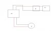
but heres what i got, ive got 2 batteries in parallel for a total of 6 volts /8Ah
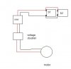
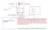
(6v/4ah x2 ) i have a remote controlled boat "that" ran on 4 AA batteries , i took it all out, put it in a homemade boat. Im sure i cant double the voltage into the reciever, with out frying it. So i want to double the output off the leads to the motor, assuming that this initially ran from 4 AA that the current is not very high. granted this could and probly will burn up the motors, im ok with that as all upgrade them later...
Here's what i would like :
1) double voltage give or take a few...
2) handle 2-3 amp or more...
3) have no ic's or transformer if possible...
4) least amount of componets as possible...
Ive looked at the max1044 but didnt see max current it could handle,probly over looked it ,(im good at that )
)
any schematics or hints ,tips , or advice greatly appreciated
and as always ***** THANKS *****
if needing current draw from circuit i will check it and repost if needed :
first i searched the site but didnt see any circuit for what i need ,may of been in there but didnt see one .
but heres what i got, ive got 2 batteries in parallel for a total of 6 volts /8Ah
(6v/4ah x2 ) i have a remote controlled boat "that" ran on 4 AA batteries , i took it all out, put it in a homemade boat. Im sure i cant double the voltage into the reciever, with out frying it. So i want to double the output off the leads to the motor, assuming that this initially ran from 4 AA that the current is not very high. granted this could and probly will burn up the motors, im ok with that as all upgrade them later...
Here's what i would like :
1) double voltage give or take a few...
2) handle 2-3 amp or more...
3) have no ic's or transformer if possible...
4) least amount of componets as possible...
Ive looked at the max1044 but didnt see max current it could handle,probly over looked it ,(im good at that
)any schematics or hints ,tips , or advice greatly appreciated
and as always ***** THANKS *****
if needing current draw from circuit i will check it and repost if needed :