Electro Tech is an online community (with over 170,000 members) who enjoy talking about and building electronic circuits, projects and gadgets. To participate you need to register. Registration is free. Click here to register now.
Welcome to our site! Electro Tech is an online community (with over 170,000 members) who enjoy talking about and building electronic circuits, projects and gadgets. To participate you need to register. Registration is free. Click here to register now.
I don't get how to calculate the voltage division to divide the main voltage between n number of resistors. Can anybody please explain the principles and theory of voltage dividers.
I don't get how to calculate the voltage division to divide the main voltage between n number of resistors. Can anybody please explain the principles and theory of voltage dividers.
First find the equivalent resistance through the entire resistor network, then use: I = V/R to get the current through the entire network. From there you can find the voltage drop on any resistor using V=I*R. If any resistors make a formation, you'll need a special formula.
If you only have two series resistors things are much easier. If you know the supply voltage, and you want to get this divided voltage from "Ra," just use this...
Vdivided = (Vsupply) (Ra)/(Ra + Rb)
...so you can see--for example--if Ra and Rb are equal, your voltage is divided by two.
Current in divider = total voltage/total resistance (ie R1+R2+R3...)
Multiply this current by each resistor value to find the voltage drop across it and then just add the potential differences up from ground voltage to find the voltage at any point you're interested in.
Yeah, I was using ohms law for the circuit current (which is constant in series).
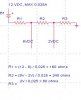
I had to design a circuit that had a 12 volt source, and 25mA. There had to be three resistors, with a voltage drop of 8VDC between R1 and R2, and a voltage drop of 2VDC between R2 and R3.
This is the way I did it, Is there an easier way? It seems to work.
The resistors run nice and cool. The total circuit power consumption is
Pt = 12V * 0.025 = 300mW
Considering I'm using half watt (500mW) resistors.
If we multiply 12 volts by 0.025 amps (25mA), we get 0.3 watts (300mW).
This means that a 1/4 watt resistor won't work without problems.
Use 1/2 watt resistors.
Well he's using 3 different resistors and the biggest drop across any of them is 6v, with an I of 25ma, so max power in that would be 150mw..
Very Happy
Ignoring TOTAL Circuit power consumption (which doesn't displace across any of the resistors. Each resistor has a power of less than 250 mW; so I can use 1/4 watt resistors safely.
Ignoring TOTAL Circuit power consumption (which doesn't displace across any of the resistors. Each resistor has a power of less than 250 mW; so I can use 1/4 watt resistors safely.
Single resistor = 300mw/500mw = 60% of its maximum power rating
3 Resistors, Max power = 150mw/250mw = 60% of max power rating
So using 3 1/4 rated resistors gives the same margin of power useage as a single 1/2 watt which you would find acceptable, looks the same to me
Single resistor = 300mw/500mw = 60% of its maximum power rating
3 Resistors, Max power = 150mw/250mw = 60% of max power rating
So using 3 1/4 rated resistors gives the same margin of power useage as a single 1/2 watt which you would find acceptable, looks the same to me
Because in Canada, 1/2 watt is the closest to 1/4 watt resistors.
If in your area, you can find any resistor that can handle 300mW and the maximum resistor rating is less than 1/2 watt, I like to see a picture. and don't show me a 1/4 watt one.
so how does 150mW enter the picture when the wattage we are dealing with is 300mW?
The only way that 1/4 watt resistors can be used is to increase the resistance of at least 1 resistor.
If in your area, you can find any resistor that can handle 300mW and the maximum resistor rating is less than 1/2 watt, I like to see a picture. and don't show me a 1/4 watt one.
I can't provide any Kodak moments, but to put things in focus: 300mW is the total combined dissipation on R1+R2+R3. Right now, only the individual dissipations are in the limelight. In fact, you could crop things down to a 1/8th watt resistor for R3 and R1. Panning back to the diagram, windozeuser said his supply is 12V @ 25mA constantly, so our money shot is:
Zooming in on the individual dissipations, you'd get (25mA)²*160Ω = 100mW on R1; (25mA)²*240Ω = 150mW on R2; and (25mA)²*80Ω = 50mW at R3 for the photo finish. A snapshot of windozeuser's results reveals these power figures are double-prints. The 300mW figure doesn't steal the spotlight until all three dissipations are added up.
Just be sure to use my favorite resistor type: carbon film. (One last photography pun there. :lol: )
This site uses cookies to help personalise content, tailor your experience and to keep you logged in if you register.
By continuing to use this site, you are consenting to our use of cookies.