EN0
Member
Hey Everyone,
Just want to make sure I'm doing this right.
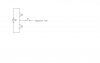
Suppose I have a voltage divider like in the first attachement. You'll see that R1 = 680Ω and R2 = 20k giving me an output voltage of 8.7V [Vout = R2/(R1+R2)]. Now, to calculate the output current of the voltage divider, you do the following: Iout = Vin/(R1+R2). So my current output is approximately 435μA. Let's say I want to have 2.5μA for my output, I simply add a resistor like in the second attachment. What would the output current be now? Also, wouldn't there be a voltage drop across R3 so I would have to make the voltage a bit larger to compensate for that drop? Ignoring the voltage drop, this is what I did: 435μA - 2.5μA = 437.5μA. So, 8.7V / 437.5μA = 19885.71429Ω ≈ 20k.
Please let me know if I'm doing this right! This is to get the correct base current and voltage to an NPN transistor.
Just want to make sure I'm doing this right.
Suppose I have a voltage divider like in the first attachement. You'll see that R1 = 680Ω and R2 = 20k giving me an output voltage of 8.7V [Vout = R2/(R1+R2)]. Now, to calculate the output current of the voltage divider, you do the following: Iout = Vin/(R1+R2). So my current output is approximately 435μA. Let's say I want to have 2.5μA for my output, I simply add a resistor like in the second attachment. What would the output current be now? Also, wouldn't there be a voltage drop across R3 so I would have to make the voltage a bit larger to compensate for that drop? Ignoring the voltage drop, this is what I did: 435μA - 2.5μA = 437.5μA. So, 8.7V / 437.5μA = 19885.71429Ω ≈ 20k.
Please let me know if I'm doing this right! This is to get the correct base current and voltage to an NPN transistor.