Continue to Site

Welcome to our site!

Electro Tech is an online community (with over 170,000 members) who enjoy talking about and building electronic circuits, projects and gadgets. To participate you need to register. Registration is free. Click here to register now.

  • Welcome to our site! Electro Tech is an online community (with over 170,000 members) who enjoy talking about and building electronic circuits, projects and gadgets. To participate you need to register. Registration is free. Click here to register now.

Voltage behavior from BLDC ESC

Status
Not open for further replies.

Rusttree

Member
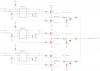
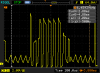
I'm hoping someone can help me understand why the o-scope trace looks the way it does from my speed controller. This is for a 3-phase BLDC motor. See the attached images of the voltage trace of one of the phases and my circuit.

The middle part of the trace is where the PWM power is on for that phase. Each PWM duty cycle peaks at 12V (the supply voltage), but then immediately begins to slope down. The next duty cycle peaks at 12 again and then slopes down again. It's like resistance is being added to the line. I don't see why the voltage doesn't hold steady at 12V for the entire duty cycle.

I'm using complimentary PWM, so I don't think it's the booster cap running out of juice. The FETs are BUK7535-55A with IR2011 drivers. The PWM is at 7.8kHz.

Any thoughts or ideas?

Thanks!
 

Attachments

  • esc.png
    esc.png
    29.1 KB · Views: 200
  • NewFile0.png
    NewFile0.png
    5.6 KB · Views: 167
Last edited:
It's due to the motor winding inductance. When a voltage is applied to the winding via a FET the current through the winding and FET ramp up at a rate inversely proportional to the inductance. That results in a ramped voltage drop due to the drain-source 'on' resistance of the FET.
 
Ok, I see. So that kind of behavior is expected.

I was hoping it was the reason why I can't spin the motor as fast as I should be able to (50% duty on the 1500Kv motor only spins at 5000rpm). Something else is limiting the current, then. Any thoughts on that? I'm considering I might need better hardware components.
 
Something else is limiting the current, then. Any thoughts on that?
Well your trace only shows voltage, and doesn't indicate where its being monitored. More clues needed! What is the motor winding resistance? What is the quoted 'on' resistance of the FETs? Any idea of the winding inductance?
 
I'm measuring the voltage directly from one of the wires of the motor. Basically, the same place that I get BEMF data for zero-crossing detection. The winding resistance of the motor is very small. Smaller than my ohmmeter is accurate to read, so I can't get a good measurement. I know there are tricks to read very small resistances, so I can get that information if necessary. No idea about the winding inductance. Is there a good method to measure that? Here's the product page for the motor I purchased:
**broken link removed**

I hooked up the motor to a commercial ESC and it spun right up to the Kv rating for the motor, so I know the motor itself is not at fault.

The Rds-on resistance of the FETs is in the 30-70mOhm range. I know that's a little high, but is that enough to reduce the max RPM by so much?
 
The Rds-on resistance of the FETs is in the 30-70mOhm range. I know that's a little high, but is that enough to reduce the max RPM by so much?
From what I gathered from a quick google, the motor resistance is ~ 100mOhm. So the FET on-resistance is a significant fraction of that and may well account for some of the revs loss you experience.
 
Last edited:
Have you measured the motor current along with the voltage? Without knowing the current is difficult to know what's happening.
 
Last edited:
Status
Not open for further replies.

New Articles From Microcontroller Tips

Back
Top