Continue to Site

Welcome to our site!

Electro Tech is an online community (with over 170,000 members) who enjoy talking about and building electronic circuits, projects and gadgets. To participate you need to register. Registration is free. Click here to register now.

  • Welcome to our site! Electro Tech is an online community (with over 170,000 members) who enjoy talking about and building electronic circuits, projects and gadgets. To participate you need to register. Registration is free. Click here to register now.

voice activated FM transmitter

Status
Not open for further replies.

chikedef

New Member
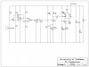
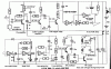
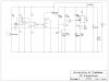
The aim of this project is to develop a miniaturized low power voice activated FM transmitter to be used in special applications such as room monitoring (in this case baby, patients or disabled persons listening device). it must transmit in the FM broadcast band.
 

Attachments

  • FM transmitter.jpg
    FM transmitter.jpg
    430.8 KB · Views: 835
Your circuit does make sense to me. The op amp stages will work ok to detect the voice and create a "transmit" function at the cathode of D1, but after that point it goes wrong. You then feed this transmit command into the modulation port of a simple audio FM transmitter. This is the wrong thing to do. The "transmit" function should be turning the transmitter on and off, not modulating it. I presume you want the audio to modulate the transmitter, but in order to do this, you need to feed amplified audio to it. To do this, I think you should make a connection through a coupling capacitor from the electret mic over to the junction of R9 and R10. You should also disconnect R7 and R8 from this junction. With these changes you have an FM transmitter that can be modulated from the mic, and you have an audio detector that isn't doing anything yet. Now, you need to attach a switch of some sort, perhaps a transistor switch, to the junction of R7 and R8 and put this switch in series with the power supply to the Q2 and Q3 stages.
 
Here is a Voice Operated FM transmitter:
 

Attachments

  • VoxCct.gif
    VoxCct.gif
    62.3 KB · Views: 492
Last edited:
voice activated transmitter

RE : RadioRon

thanks l have done the modifications in the attached circuit and am looking simulation software for the circuit. other views are welcome
 

Attachments

  • FM transmitter.jpg
    FM transmitter.jpg
    162.3 KB · Views: 476
The radio transmitter part is not good:
1) Its antenna is connected directly to its tuned circuit so its frequency will change is something moves toward or away from the antenna.
2) Its frequency will change as its battery runs down.
3) The value of R14 is much too high and/or the value of R13 is much too low.
 
thanks so what are your recomended resistor values to the above., and how can l modify the circuit for it to perform better. which software can l use to simulate the circuit. on the battery how can l improve on the circuit for it to maintain constant frequency during transmiting throughout the battery lifespan.
 
R14 is usually 100 ohms to 470 ohms. R13 is usually 47k to 100k ohms.

If you add an RF amplifier transistor between the oscillator and the antenna then the frequency will not change if something moves toward or away from the antenna.
The circuit board must be suspended in a metal box connected to 0V.

Use a low-dropout 5V voltage regulator IC to power the oscillator and the preamp.

I use the free simulation software called LTspiceIV from Linear Technology.
 
RE : RadioRon

thanks l have done the modifications in the attached circuit and am looking simulation software for the circuit. other views are welcome

The modifications are correct, you now have a topology that makes sense. I recommend that you follow Audioguru's recommendations on improving the transmitter section.

Your switch, Q1, is generally the right idea but not optimal. One problem that will occur is that the voltage divider of R7 and R8 will reduce the voltage presented to the base of Q1 to a very low value and so the emitter of Q1 will always be too low a voltage. You will need to improve the design of this switch. The most common successful configuration for a bipolar transistor switch like this is to use a PNP transistor (eg. 2N3906 or any other) with emitter as input and collector as output. Unfortunately, this PNP arrangement will require that your control signal be "active low" instead of active high as it is now. In other words, the base of the PNP switch must be pulled low through a resistor to turn the switch on, not high through a resistor as you have it now. However, you can easily reverse the polarity of your control signal by reversing the direction of D1. For the suggested configuration, you would also need to move R8, from its current location, to making a connection from +9V to the junction of D1 and C3. I suggest that R8 would become 100K ohms and R7 should become 18K ohms. C3 may be OK at 47 uF, but you may find this too small, perhaps 100uF would provide a longer "hang time" for the transmit function.
 
The clever part of my circuit is this:
It produces a beep when not transmitting so that you can detect the frequency on which it will transmit when turned on.
A VOX transmitter is much more complicated than you think and it took many hours to perfect the design above.
It's pointless re-inventing the wheel.

The circuit produced by the original poster has so many faults and mistakes that it will never work. He obviously has absolutley no idea what he is doing.
 
Last edited:
thanks will make the resistor adjustment and for reverse biasing the diode how will the transistor be switched on? can you eleborate on that
 
@ RadioRon

thanks for the reply on the voice activation part, sorry l made this a private message hope you dont mind. l was thinking on your suggestion to reverse bias the diode D1 on my proposed design how will the activation signal reach the transistor. l was thinking of removing the potential divider that is R7 & R8 from the arrangement to increase the voltage reaching Q1. in addition can you elaborate further on your suggested arrangement of connecting +9V to diode junction
 
Re: Audioguru

I use the free simulation software called LTspiceIV from Linear Technology.

have the LTspice but since am wondering if i can find a mike for my voice activated transmitter or a relevant signal generator and other ICs like the LM1458 which is in my voice activation switch
 
Most people use a very good performance inexpensive electret mic for FM transmitters. It is powered from a filtered supply through a 10k resistor and needs a low noise preamp (an old LM1458 is too noisy (hissss).
I use low noise wide bandwidth inexpensive TL07x audio opamps for preamps.
 
Tl 07x

RE audioguru

thanks for the that idea but can l replace the TL07x series with the TL08x series since l can't get the 07 series locally. what other recommendations do you have for the preamp?
 
A TL071 is a TL081 that was selected for low noise. Maybe you will be lucky to find a TL081 that also has low noise because an entire production run had low noise.
An OPA134 opamp is better.
 
RE : Audioguru
thanks for that. i will look for that and replace, apparently it seems my mike is not picking any signal. l didnt get right the suggestion by RadioRon, can you ellaborate if you got it that is making the +9v vcc appear at the emitter once a signal at Q1. i have qouted RadioRon below

The modifications are correct, you now have a topology that makes sense. I recommend that you follow Audioguru's recommendations on improving the transmitter section.

Your switch, Q1, is generally the right idea but not optimal. One problem that will occur is that the voltage divider of R7 and R8 will reduce the voltage presented to the base of Q1 to a very low value and so the emitter of Q1 will always be too low a voltage. You will need to improve the design of this switch. The most common successful configuration for a bipolar transistor switch like this is to use a PNP transistor (eg. 2N3906 or any other) with emitter as input and collector as output. Unfortunately, this PNP arrangement will require that your control signal be "active low" instead of active high as it is now. In other words, the base of the PNP switch must be pulled low through a resistor to turn the switch on, not high through a resistor as you have it now. However, you can easily reverse the polarity of your control signal by reversing the direction of D1. For the suggested configuration, you would also need to move R8, from its current location, to making a connection from +9V to the junction of D1 and C3. I suggest that R8 would become 100K ohms and R7 should become 18K ohms. C3 may be OK at 47 uF, but you may find this too small, perhaps 100uF would provide a longer "hang time" for the transmit function.
 
Status
Not open for further replies.

Latest threads

New Articles From Microcontroller Tips

Back
Top