Continue to Site

Welcome to our site!

Electro Tech is an online community (with over 170,000 members) who enjoy talking about and building electronic circuits, projects and gadgets. To participate you need to register. Registration is free. Click here to register now.

  • Welcome to our site! Electro Tech is an online community (with over 170,000 members) who enjoy talking about and building electronic circuits, projects and gadgets. To participate you need to register. Registration is free. Click here to register now.

VHF Aeial

Status
Not open for further replies.

Gregory

Member
I have a Vhf Marine radio aerial and the Coax is broken from the aerial
Can you advise me where the Screaning wire is soldered to on the aerial and the inner wire
I will supply a Digram of the aerial that also has a 2.8 pf Ceramic Disc Cpacitore
 

Attachments

  • IMGVHF Aerial.jpg
    IMGVHF Aerial.jpg
    791.6 KB · Views: 408
I don't follow your drawing at all. What kind of antenna do you have? Any chance you can post a picture of it?
 
The drawing IS the aerial, looks like a based loaded whip to me, but I've never seen anything with a capacitor on it like that.
 
I have attached a photo of the aerial which is 2.3 M in length
The small wire in the photo is the cap which goes to a center tapping of the windings and the other wire is at the start if the winding.
The wirer at the end of the winding goes up the aerial and comes out at the base of the winding at the top as shown in the photo.
The wirer at the corner of the paper in the photo which also has red texture on this area is where the wirer comes out of of the aerial which continues up the aerial.
With regards the coax, where dos the screen wire solder to and where dos the center of the coax solder to in relation to the capacitor.

Thank you greg
 

Attachments

  • IMG_3076.JPG
    IMG_3076.JPG
    370.1 KB · Views: 326
  • IMG_3078.JPG
    IMG_3078.JPG
    319.4 KB · Views: 325
  • IMG_3080.JPG
    IMG_3080.JPG
    567.9 KB · Views: 319
I'm thinking a shunt-fed 5/8λ or 3/4λ like is on my boat. AFAIK, the center conductor of the coax attaches to the capacitor, and shield of the coax attaches to the bottom end of the coil. Try it that way, and then use a VHF SWR meter to check it in the marine band.

I recently replaced one of those antennas, and it was not expensive.

Read this note "DC Ground: YES - however, the antenna will read "open circuit" when tested with ohmeter. " on this **broken link removed**
 
After seeing those pics I'd recommend a new one, all those green turns on the larger picture are probably shorted together, at the very least the wire needs to be replaced.
 
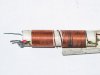
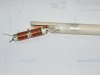
I find it VERY strange that you have SO MANY turns for a VHF antenna !!!!

That looks much more like a CB antenna (althrough a 8.2pF cap seems nore suited to a VHF aerial !!!)

What i suggest you is to replace everything with a J-pole antenna !

A single length of 300 ohm TV antenna twin-lead correctly cut and you'll have a working antenna (no capacitors).

**broken link removed**

The antenna shown is cut for the 146 MHz amateur radio band. For the marine band, try cutting the whole antenna at 50 3/8" instead of 54", the bottom right length at 1 1/8 rather than 1 1/4 (that solder point may move dependant of the SWR) and the next length cut at 14 1/4 rather than 15 1/4. The 1/4 inch gap remains the same.

Once the J-pole is built, simply slide it in the fiberglass radome, secure it in place by the coax and you're done !

Try it out ! It's cheap !

edit: The J-pole is an end-fed halfwave antenna. The bottom right 15 inch wire, along with it's corresponding length on the left conductor acts as am impedance transformer (an end-fed halfwave is a high impedance antenna and the transformer adapts this high impedance to 50 ohms) and the remaining length on the left conductor is the antenna itself.

I'm not sure about the top right unconnected portion of wire. Althrough it seems to have no effect on the antenna, being unconnected, it may help make the antenna sightly more broadband by being closely coupled to the left portion of wire (the antenna itself) and by this coupling, rising the effective diameter of the antenna. (A large diameter copper pipe is more broadband than a thin wire.)
 
Last edited:
Status
Not open for further replies.

New Articles From Microcontroller Tips

Back
Top