Hi all,
I m doing a school project which I need to design a Very Low Frequency, High Voltage supply for testing cables.
Problem: Setting up a PWM to drive the MOSFETs to form a 0.1Hz sine wave. Please advice. The detail information is shown below:
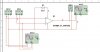
320V DC --> inverter which is driven by a PWM to produce a sine wave output. A low-pass filter will be added at the output for filtering purposes.
Question is how can I solve the PWM circuit?
The PWM will be driving by two function generators, 1 trianglar wave of 5kHz and a size wave of 0.1Hz. How can I use a comparator or op-amp to produce a square wave to drive my MOSFET in order to achieve the low freq Sinewave.
Why is my PWM show in attachment 3 not producing a signal i desire?
Please help.
I m doing a school project which I need to design a Very Low Frequency, High Voltage supply for testing cables.
Problem: Setting up a PWM to drive the MOSFETs to form a 0.1Hz sine wave. Please advice. The detail information is shown below:
320V DC --> inverter which is driven by a PWM to produce a sine wave output. A low-pass filter will be added at the output for filtering purposes.
Question is how can I solve the PWM circuit?
The PWM will be driving by two function generators, 1 trianglar wave of 5kHz and a size wave of 0.1Hz. How can I use a comparator or op-amp to produce a square wave to drive my MOSFET in order to achieve the low freq Sinewave.
Why is my PWM show in attachment 3 not producing a signal i desire?
Please help.
Attachments
Last edited:
