Mr RB
Well-Known Member
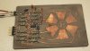
I got bored one weekend and tried to make a one-chip capacitor pad sensor using just a 10 cent 74ACT14 hex schmidt inverter chip. The pad sensor was to be stand alone module so it has 6 oscillator outputs, and any PIC controller etc can just check the 6 frequencies on the output pins to see if a pad was activated.
I etched some copper pads on a PCB and used each pad as the capacitor, connected to inverter input and each inverter has one 150k resistor as feedback to make it oscillate, a very common inverter oscillator.
It worked but not great. The oscillators didn't always start up as the pad capacitance was too low. I patched in some 22pF caps to test and the oscillators stabilised but then sensisitvity was not good. I was able to detect finger at 5mm from the pad, but the low sensitivity meant the freq was only a few percent lower, so I wouldnt call it a reliable sensor. With the finger right on the pad (just paper between) it was mostly reliable.
The problem is that a schmidt inverter oscillator needs to oscillate the cap voltage from 1/3Vcc to 2/3Vcc which takes a bit of power at 300kHz. The 74ACT14 althoguh having good cmos specs was not up to self starting 6 high-freq power oscillators all at the same time, problems with latchup, refusing to start etc.
Another problem was that I connected the 6 outputs with no buffering, I just used 6x 39k resistors to the output pins, so when the output was loaded with a scope etc sensitivity was reduced again. Anyway it was worth a try for a 1 chip system.")
The Microchip 'Mtouch' app notes use a comparator oscillator which needs much less power and is more sensitive, is buffered and better self starting.
Also my pad design wasnt great, the pads are a little small and I didn't have any ground tracks near the pad for the finger to capacitively couple. The early Microchip app note shows a good pad design with a small ground pad in the centre, and then the pad around that. That gives better sensitivity. With a well designed comparator oscillator you can just use plain pads though, like the new Microchip app notes.
If I was really going to do it again i'd use 3 dual comparator ICs for more sensitive oscillators and a hex inverter as the output buffer. Hardly a one chip solution... especially when you can get PIC16F722 for $1 that has 16 Mtouch capacitor sense modules built in AND a PIC to go with it.
I etched some copper pads on a PCB and used each pad as the capacitor, connected to inverter input and each inverter has one 150k resistor as feedback to make it oscillate, a very common inverter oscillator.
It worked but not great. The oscillators didn't always start up as the pad capacitance was too low. I patched in some 22pF caps to test and the oscillators stabilised but then sensisitvity was not good. I was able to detect finger at 5mm from the pad, but the low sensitivity meant the freq was only a few percent lower, so I wouldnt call it a reliable sensor. With the finger right on the pad (just paper between) it was mostly reliable.
The problem is that a schmidt inverter oscillator needs to oscillate the cap voltage from 1/3Vcc to 2/3Vcc which takes a bit of power at 300kHz. The 74ACT14 althoguh having good cmos specs was not up to self starting 6 high-freq power oscillators all at the same time, problems with latchup, refusing to start etc.
Another problem was that I connected the 6 outputs with no buffering, I just used 6x 39k resistors to the output pins, so when the output was loaded with a scope etc sensitivity was reduced again. Anyway it was worth a try for a 1 chip system.
The Microchip 'Mtouch' app notes use a comparator oscillator which needs much less power and is more sensitive, is buffered and better self starting.
Also my pad design wasnt great, the pads are a little small and I didn't have any ground tracks near the pad for the finger to capacitively couple. The early Microchip app note shows a good pad design with a small ground pad in the centre, and then the pad around that. That gives better sensitivity. With a well designed comparator oscillator you can just use plain pads though, like the new Microchip app notes.
If I was really going to do it again i'd use 3 dual comparator ICs for more sensitive oscillators and a hex inverter as the output buffer. Hardly a one chip solution... especially when you can get PIC16F722 for $1 that has 16 Mtouch capacitor sense modules built in AND a PIC to go with it.