Continue to Site

Welcome to our site!

Electro Tech is an online community (with over 170,000 members) who enjoy talking about and building electronic circuits, projects and gadgets. To participate you need to register. Registration is free. Click here to register now.

  • Welcome to our site! Electro Tech is an online community (with over 170,000 members) who enjoy talking about and building electronic circuits, projects and gadgets. To participate you need to register. Registration is free. Click here to register now.

Variable resistor connection

Status
Not open for further replies.

ThomsCircuit

Well-Known Member
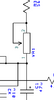
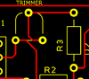
Im using these fixed trim pots and i want to connect them correctly. in the schematic (trimpot1) pin 1 is connected to the cap and 2 is to the resistor. Does it matter if i connect to pin 2 from the resistor then 3 or do i need to connect to pin 3 then 2? From what i read it appears it does not matter because pins 2&3 are simply jumped together when used.
 

Attachments

  • trimpot1.png
    trimpot1.png
    4.3 KB · Views: 186
  • trimpot2.png
    trimpot2.png
    6.8 KB · Views: 193
It makes no difference at all.

I would advise generally using somewhat wider PCB tracks, unless there is a good reason not to.
 
I would advise generally using somewhat wider PCB tracks,
Thank you. A member of this group helped me build this. He was incredibly detailed and extremely helpful. I am all for beefing things up. I actually widened the ground and supply tracks on my own. This is but a very small 50x30mm board. It has double copper pours. What size would you have used?
 
You can use 0.015 to 0.030" if you have room (especially if you are etching your own. If you are down to the 0.010 range or below, you are getting to the limits of rapid prototype pcb house's capabilities snd there is really no reason to do that unless you have very narrow pitch, high pin-count chips.

I generally use 0.015 to 0.020" for signals and 0.030 to 0.050" for power rails.
 
A trimpot usually has a CW on it for fully counter-clockwise ans so should a schematic.

A volume control for example would have minimum resistance a the CW position,

A pot that sets gain, lets say you want the resistance to go from 0 to 10K going CW. The CCW and the wiper should be tied together.
it;s actually done that way for reliability. If the pot was set to 4K, does it matter that 0-4K sections are shorted. No.
 
Status
Not open for further replies.

Latest threads

Back
Top