Continue to Site

Welcome to our site!

Electro Tech is an online community (with over 170,000 members) who enjoy talking about and building electronic circuits, projects and gadgets. To participate you need to register. Registration is free. Click here to register now.

  • Welcome to our site! Electro Tech is an online community (with over 170,000 members) who enjoy talking about and building electronic circuits, projects and gadgets. To participate you need to register. Registration is free. Click here to register now.

Using PIC16F84 to replace PIC10F204 in my project. Help?

Status
Not open for further replies.

orangekitty

New Member
Hi, I initially am constructing a circuit according to Microchip's App Note AN958 using PIC10F204. But I cannot find a programmer for it. So I changed to a more common PIC like PIC16F84 but I do not know how to plugin the potentiometer to vary the triac. I also don't know which pins to substitute with which and I've got a very simple pwm source code from the other site for 16F84 but do not know how to implement into my circuit. Help!
 

Attachments

  • PWM-16F84.txt
    1.5 KB · Views: 196
Use a Pickit 2 programmer from Microchip, or a clone if you must. Will program all the PIC10f's, up through some of the early PIC32's.
 
But PIC2Kit cannot porgram my PIC10F204 no matter how I tried. So now i resort to PIC16F877A. Don really know how's the coding like. Help?
 
The Pickit2 can program the 10F204.

Mike.

It sure can you manually set the chip

But you no how hard it is to do things manually

If it's not automatic then it not working LOL
 

Attachments

  • you_set.JPG
    you_set.JPG
    37.7 KB · Views: 305
But PIC2Kit cannot porgram my PIC10F204 no matter how I tried. So now i resort to PIC16F877A. Don really know how's the coding like. Help?

As others point out, PICKIT2 can program the 10F204.
The problem you may be having, when trying to program the 10F204, could be due to a mis-understanding of what is actually required for connection with this device...

It can be assumed that you are likely to be using the 10F DIP-8 package, otherwise you would probably be using ICSP or some form of SOT23-6 / DFN to DIP-8 adapter, which converts the irregular pinout of this 10F device family, to the more familiar pinout of something like the 12F629/675/683 etc.

Confusion can arise from familiarity with previous products, such as the previously mentioned 12F629/675/683, which share the same pin designations as the 12F508/509 and others commonly used in the past.

IIRC, the production of the 10F devices neccessitated a shift from the normal pinouts due to the silicon dies being primarily aimed at SOT packages, but provisions were also made to provide a DIP-8 package, for development. EDIT - (This particular 10F DIP-8 development package still does not follow the pinout of the previous DIP-8 devices!)

But, it's an 8 pin PIC..... it should fit where every other 8 pin PIC fits - right?

Datasheets hold the key...
 
Last edited:
Nope it don't fit in with the rest the pin out is not the same and if you tried like a 12f you hooked it up wrong always read the data sheet first

I still do every time I hook up a chip even if I'm sure I'll double check with the data sheet
 
Mickster said:
But, it's an 8 pin PIC..... it should fit where every other 8 pin PIC fits - right?


be80be said:
Nope it don't fit in with the rest the pin out is not the same and if you tried like a 12f you hooked it up wrong always read the data sheet first

That was a rhetorical question Burt, but maybe it was mis-placed within my previous post....perhaps it should have been placed before the description as to why the pinout is different for this particular device.

But the advice still firmly stands to always check the datasheets!!
 
I have not been able to program a PIC10F with a Pickit2, no matter how I try.

Which methods have you tried Colin?

I have some 10F222's in DIP form:
They program in a LPC Demo Board, using a crude converter made from stripboard, a socket & some header pins.
They program simply on a breadboard with just a jumper-style cable connected directly to PICkit2.
They program in-circuit, on a few simple stripboard projects.
They program using the AC163020 from Microchip, either standalone, or plugged into the LPC Demo Board.
I also have some in SOT23-6 form:
They program, along with some 10F202's & 206's, using the AC163020 standalone, or plugged into the LPC Demo Board.
They program, along with the 10F202's & 206's, using the AC163021 SOT23-6 to DIP-8 adapter PCB, on breadboard with the jumper cable & also plugged into the LPC Demo Board directly, since the adapter PCB converts the pinout to the same as that found on such devices as the 12F's.

HTH.
 
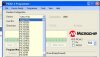
I used UP00B to try to program the PIC10F204. It didnt work.. =( But anyways, I decided to forget about that PIC. Now I'm using PIC16F877A. I need to write an analog input command for this PIC but it can compile in Microcode Studio but when I want to write, it fails. I also do not know if my source code is correct.

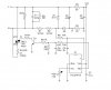
I basically want to generate a PWM signal to control my triac which then controls my the heat output of my load. The duty cycle of the PWM is controlled by a potentiometer which is connected to the analog input of the PIC.

Help. My supervisor threatens to fail me. =(

My circuit is based on Microchip App Note AN958 but I have made a few adjustments.

My source code that I;ve written so far:

DEFINE OSC 20
DEFINE ADC_BITS 8
DEFINE ADC_CLOCK 3
DEFINE ADC_SAMPLUS 50

ANI VAR byte

TRISA = 255
TRISB = 0
ADCON1 = 0


IF (anI==0) THEN PWM PORTB.3,0,1000

IF ani<>0 tHEN goto run


run:


IF (ani > 0) AND ani <= 50 THEN pwm PORTB.3,50,1000
IF (ANI > 15) AND (ANI <= 30) THEN pwm PORTB.3,30,1000
IF (ANI > 30) AND (ANI <= 45) THEN pwm PORTB.3,45,1000
IF (ANI > 45) AND (ANI <= 60) THEN pwm PORTB.3,60,1000
IF (ANI > 60) AND (ANI <= 75) THEN pwm PORTB.3,75,1000
IF (ANI > 90) AND (ANI <= 105) THEN pwm PORTB.3,105,1000
IF (ANI > 105) AND (ANI <= 120) THEN pwm PORTB.3,120,1000
IF (ANI > 120) AND (ANI <= 135) THEN pwm PORTB.3,135,1000
IF (ANI > 150) AND (ANI <= 165) THEN pwm PORTB.3,165,1000
IF (ANI > 165) AND (ANI <= 180) THEN pwm PORTB.3,180,1000
IF (ANI > 180) AND (ANI <= 195) THEN pwm PORTB.3,195,1000
IF (ANI > 195) AND (ANI <= 210) THEN pwm PORTB.3,210,1000
IF (ANI > 225) AND (ANI <= 240) THEN pwm PORTB.3,240,1000
IF (ANI > 240) AND (ANI <= 255) THEN pwm PORTB.3,255,1000


ADCIN 0, ani
pauseus 50

end
 

Attachments

  • newcct.jpg
    newcct.jpg
    35.4 KB · Views: 511
Status
Not open for further replies.

Latest threads

New Articles From Microcontroller Tips

Back
Top