Continue to Site

Welcome to our site!

Electro Tech is an online community (with over 170,000 members) who enjoy talking about and building electronic circuits, projects and gadgets. To participate you need to register. Registration is free. Click here to register now.

  • Welcome to our site! Electro Tech is an online community (with over 170,000 members) who enjoy talking about and building electronic circuits, projects and gadgets. To participate you need to register. Registration is free. Click here to register now.

Using P-Channel MOSFET to speed control Motor

Status
Not open for further replies.

FireAce

New Member
Greetings, this one is prob a no brainer, but it sure has me stumped at the moment.

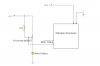
Attached is a diagram of what I'm trying to do, but it doesnt quite work. I'm using a wireless receiver to power a model truck I'm custom building. The receiver used to power a motor, but of much smaller amp load then I am wanting to use.

The diagram shows a test I was trying on the bench, which worked with a smaller motor, but not when i attached the actual motor I'm trying to use.

The Receiver motor outs are this:
Red is connected directly to positive voltage in
Black pulls low as throttle goes up, giving speed control from 0 to100%
 

Attachments

  • Motor Control.jpg
    Motor Control.jpg
    17.5 KB · Views: 199
The usual lack of info. Can't answer your question without the MOSFET model number and the current draw of the actual motor.
 
Oh ya, I remembered what I forgot in the middle of my hot shower.

The MOSFET is a IRF4905.
The motor is actually two 6v motors in parallel from a Meccano building set. I wouldnt think the amp draw would be that much.

The circuit is producing, giving me speed control, but VERY MUCH under powered. The two 6v motors wont even move, they just sing.
 
Can you measure all the voltages when it's trying to drive the motors (including the supply)? That will help isolate the problem.

The problem could be the MOSFET. It requires a Vgs of 10V for full turn-on and you are only applying 6V. You may need to use a logic-level type MOSFET which fully turns on at a Vgs of 5V or less.
 
From further testing, I dont think this will work. Somehow I need to make the receivers motor output run a PWM, which can in turn hook to an IRF530, as shown in link below, but without the 100k pot

**broken link removed**
 
Last edited:
If you Google "voltage controlled PWM" you should get some useful hits.
 
I found this one, but I cant explain Pin 3 on the 555, or what the control voltage on IC2 is referring to, could it be asking for a 10k pot?
 

Attachments

  • LM555PMW1.GIF
    LM555PMW1.GIF
    7.2 KB · Views: 172
Pin 3 is the usual output pin of the 555. It is used here only to monitor the 555 operation (optional). Here, pins 2 and 6 are instead used as the output, providing a sawtooth wave as one input to the op-amp, the other input being a control voltage (DC threshold level) set by the 10k pot. When the sawtooth crosses the threshold the op-amp output switches from one supply rail to the other. The result is a square wave with a pulse width dependent on the control voltage.
 
Thanks Alec, kinda what I figured. It does appear to be working, with a small issue.

I have the circuit running on 12v
The receiver motor output has 7v at throttle all the down, then goes to 0v as you throttle up, beings it pulls the motor to ground
IC2 in the diagram is directly attached a IRF520, and is working fine, except the 7v from the receiver is not enough to completely shut off IC2 output.

I either need a way to amplify the 7v, or a way to adjust IC2 so MOSFET gate get pulled LOW more
 
Status
Not open for further replies.

Latest threads

New Articles From Microcontroller Tips

Back
Top