Continue to Site

Welcome to our site!

Electro Tech is an online community (with over 170,000 members) who enjoy talking about and building electronic circuits, projects and gadgets. To participate you need to register. Registration is free. Click here to register now.

  • Welcome to our site! Electro Tech is an online community (with over 170,000 members) who enjoy talking about and building electronic circuits, projects and gadgets. To participate you need to register. Registration is free. Click here to register now.

using Junebug UART feature for target project

Status
Not open for further replies.

MrDEB

Well-Known Member
Using the Junebug to communicate via the UART to a daughter board(target project )
How to proceed?
setup - target is an 18F1320 or 18F452.
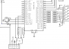
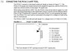
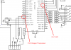
in order to use the USART do I just connect the RX and TX pins of the target to the Con 3 header or is it possible to use the ICSP header cable and a dip switch to connect the RX/TX ports.
In several schematics I see a 6 pin header used for UART - INT1, +5V, GRD, TX, RX, INT2
Any suggestions on connections
 
This is what I am wondering about connections

Want to build a development board that has an 18 pin and 40 pin sockets for target PICs, Board to have female sockets for jumpers from development board to bread board as well as a header to connect an LCD daughter board.
Want to be able to use the UART to debug code but need method to enable communication.
This is what my idea is. Is this feasible?
 

Attachments

  • UART switch.PNG
    UART switch.PNG
    31 KB · Views: 190
Hi, Mr Deb, the PICKIT2 users guide says you are only supposed to connect the VSS(GND), VDD, TX and RX pins with the PICKIT2( PG#69). Also, the power pins are necessary. If you are going to use the PICKIT2 UART Tool for debugging only, than why use the UART tool, why not the debugging tool itself? Also just looked at the schematic, in order to use the PICKIT2s UART tool, the PICKIT2 pins are to be connected to the TX, RX pins of the target chip in addition to the power pins. So according to your schematic you are not making connections for the UART Tool.
 

Attachments

  • pickit2uart.JPG
    pickit2uart.JPG
    76.9 KB · Views: 230
  • UART switch.PNG
    UART switch.PNG
    34.7 KB · Views: 291
Last edited:
going to use the Junebug, not a Pickit2. Then using the ISCP header to supply power and ground.
If you look at a schematic for the Junebug I think I decipher that the proposed switch will work. The dip switch ciontrols the ICSP header for onboard PIC or off board target PIC.
 
going to use the Junebug, not a Pickit2. Then using the ISCP header to supply power and ground.
If you look at a schematic for the Junebug I think I decipher that the proposed switch will work. The dip switch ciontrols the ICSP header for onboard PIC or off board target PIC.

Hi MrDEB, sorry i misread the schematic, the DIP switch will work( a somewhat similar procedure is done by SW6 in the Junebug). If by the Bold statement you mean that external supply will not be provided, I quote the PICKIT2(Junebug) user guide.

"When being used with the UART Tool, the PICkit 2 may not be able to supply VDD voltage
to the target depending on the application version. See the version Release Notes
in the PICkit 2 Readme file.However, even when PICkit 2 is not supplying the target
VDD, the PICkit 2 VDD pin must be connected to the target VDD voltage or it will not be
able to communicate."

So if you are not supplying external power, you need to go through the release notes, and if you are supplying external power than the Junebug power pins need to be connected as well. I say this because i needed to use external supply when i used the Junebug (PICKIT2) UART Tool.
 
Yes I am using an external supply.
Recently I incurred an issue concerning Vdd. I have a PIR connected to my target devive and the Pickit2 2 software won't load and / or write to the target pic.
Using an external supply I am having no issues except I need to still check the ON box above MCLR box.
 
In several schematics I see a 6 pin header used for UART - INT1, +5V, GRD, TX, RX, INT2

The TAP-28 board uses this pinout for the UART connector. When the UART isn't being used, the connector can be used for general-purpose I/O with 4 port pins, power and ground available.

When using the UART to communicate with other boards, sometimes an additional control line is needed to alert the other board to an incoming message.

TAP-28 Application Board

**broken link removed**
 
Hi, the ON checkbox allows the programmer to power the target device using the PICKIT2(PG#22 PICKIT2 users guide). If no external supply is detected than the PICKIT2/ Junebug will supply the power regardless of the checkbox state. Even with external supply, you still see the "ON" checkbox? If so than your Junebug is not being able to detect the external supply because on detecting an external supply, the "ON" checkbox changes to the "CHECK" checkbox for measuring the external voltage. Can you post a schematic?
 
Using the Junebug to communicate via the UART to a daughter board(target project )
In several schematics I see a 6 pin header used for UART - INT1, +5V, GRD, TX, RX, INT2

Looks like you got these connections from the TAP-28 board. When the UART is being used, power, ground, TxD and RxD only are used. When using serial coms to another board, sometimes a handshake line is needed, so INT1 and/or INT2 may be used.

If the connector is used for other purposes, 4 port pins, power and ground are available for general purpose use.


TAP-28 Info
 
I was unaware that the Tap-28 had such a switch?
Need to pour over your Tap-28 schematic again to see if I missed anything else.
 
Status
Not open for further replies.

Latest threads

Back
Top