Continue to Site

Welcome to our site!

Electro Tech is an online community (with over 170,000 members) who enjoy talking about and building electronic circuits, projects and gadgets. To participate you need to register. Registration is free. Click here to register now.

  • Welcome to our site! Electro Tech is an online community (with over 170,000 members) who enjoy talking about and building electronic circuits, projects and gadgets. To participate you need to register. Registration is free. Click here to register now.

Using Impulse Relay as Alternator

Status
Not open for further replies.

Haidy

New Member
Any ideas about using an impulse relay to alternate operation between two pumps?
The impulse relay will be energized & de energized by two pressure switches.
 
More detail! Will one pump or the other be running all the time? Will both pumps ever be on at the same time? Will both pumps ever be off at the same time?

Ken
 
More Details

The pumps will not run all the time, only one pump will run (at a time) when it receives a signal from pressure switch.
The two pumps will NEVER run together. The alternation is between them such that both operates equal number of times, ie. if pump 1 operated first time, then next time pump 2 will operate then third time pump 1 , so on.

Both will be off same time when the whole booster is switched off or when the pressure switch does not send a signal.

Pressure switch is normally opened, so when it closes one pump will run, while if it is opened the pump will stop (if it was operating).

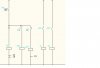
Now please find attached diagram for how i thought it maybe. I used two impulse relays but i am not sure i am right because of two reasons:

1- if PS1 was closed, R will be energized, so first NO contact will close and energize IMP1 to operate Pump1 , same time, NC contact of R will open, so will it energize IMP2 or not?? (AS i know impusle relay is energized due to transition not due to maintained power).

2- Probably i am required to do the circuit with only one impulse relay.

Thank you so much for your interest in my issue, and sory for the long details.
 

Attachments

  • ALTERNATION.JPG
    ALTERNATION.JPG
    12.1 KB · Views: 421
Sorry Haidy, I can't read the fuzzy ladder diagram. Can you re-post it in a .gif or .png format.

ken
 
Diagran Attached

The attached folder contains my diagram in a word file, paint file and autocad.
I hope you can read it.
 

Attachments

  • alternator.zip
    98.9 KB · Views: 189
My modified Circuit

Hello Sir;
I modified my circuit and attached it again, please check.
My question is : Will IMP2 be energized or de energized when PS1 closes????

I need it to be off & IMP1 to be on, this satisfies wht i want.

I hope it openes with u, if it did not, please try opening it from Paint program.
 

Attachments

  • Alt2.JPG
    Alt2.JPG
    13.9 KB · Views: 726
Both will be off same time when the whole booster is switched off or when the pressure switch does not send a signal.

First, in your original post you said there are two pressure switches. ???

In the first circuit either K1 or K2 will be on, they never both be off as long as there in power to the ladder rails. "or when the pressure switch does not send a signal"? Is there a second pressure switch that supplies power to the rails?

In the second circuit K1 will be turned on whenever the P-switches closes, but K2 will never be activated. With P-switch open there is no power to R, INP1 or INP2. With P-switch closed, R is powered opening the contact to INP2 and closing the contact to INP1 > K1.

Ken
 
RE

I am really sorry, it's only one pressure switch it was a mistake from me.

About :(Both will be off same time when the whole booster is switched off or when the pressure switch does not send a signal)

I mean both PUMPS

An now, do u have another idea to modify my circuit an make it correct?
 
I can understand "when the whole booster is switched off" how both pumps would be off, but not "when the pressure switch does not send a signal". I thought that the pressure switch's on/off was what was to cause the circuit to switch from one pump to the other. ???

Maybe you can explain in detail what you are trying to do, what the total system involves. Then, we can help solve the problem, as opposed to trying to solve the solution. ;)

ken
 
RE

Well, I am really not sure, but it is probably ( the pressure switch's on/off was what was to cause the circuit to switch from one pump to the other )

I was told that the aim is that the two pumps operate equally, so it's like what you say. But also, if pump1 operated and pressure switch kept closed during it's whole operation, then booster was turned off, the next time of operation, pump2 shall operate.
 
Still in the dark! What's the "booster" for? We're getting this request second hand? What's supposed to happen when the pressure switch goes from open to closed...and what, when closed to open?


Ken
 
RE

What's the "booster" for?

The booster is required to increase water pressure (by pumping it) when pressure switch detects drop in the system pressure.
This means, pumps are off as long as the pressure switch is opened (no pressure drop).
When drop occurs, pressure switch closes (goes from open to close),so only one pump P1 is required to operate.
If presure compensate, pressure switch opens (goes from close to open) and P1 must shut down.
When preure switch cloes again (goes from open to close), P2 must run, then whenpressure switch opens( goes from close to open) P2 must shut down, and so on.
So, the sequence required in the circuit is :
PS Normally Opened ---> P1&P2 OFF
PS closed ------------> P1 ON & (P2 OFF)
PS Opened ------------> P1 OFF & (P2 OFF)
PS closed -------------> P2 ON (P1 OFF)
PS Opened-------------> P2 OFF (P1 OFF)
PS closed ------------> P1 ON & (P2 OFF)
PS Opened ------------> P1 OFF & (P2 OFF)
.
.
.
. so on, it's a "toggling mechanism"
 
Ah, now I see! I'll have to go get some coffee and think this over. :)

Ken
 
Last edited:
Any chance that the pressure switch is a single-pole/double-throw instead of an single-pole/single-throw?

Ken
 
Do you want to try and stick with relays, or would you consider getting into more electronics...or even small programmable micro-controllers?

Ken
 
So why do you need to switch from one pump to the other each time?
Whats the purpose or reasonings for having the dual pump system?
 
Status
Not open for further replies.

Latest threads

New Articles From Microcontroller Tips

Back
Top