Continue to Site

Welcome to our site!

Electro Tech is an online community (with over 170,000 members) who enjoy talking about and building electronic circuits, projects and gadgets. To participate you need to register. Registration is free. Click here to register now.

  • Welcome to our site! Electro Tech is an online community (with over 170,000 members) who enjoy talking about and building electronic circuits, projects and gadgets. To participate you need to register. Registration is free. Click here to register now.

Using comparators with PWM

Status
Not open for further replies.

kinarfi

Well-Known Member
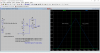
I have always thought that a comparator, LM339 /LM393), switched states when in+ and in- were equal or very near equal, spec sheet says 5 mv, yet when I create a sawtooth wave, 5oKhz, 3v to 7 v, and compare it to a rising voltage, 3 to 7, the output voltage of the LM393 is 0v, no switching, until the difference is around 736mv and full on, 14, no switching, while the difference is still 1.17 between in- and in +.
Is this normal or have it messed up something in my sim? or is it different on the bench, got go see!
Thanks,
Jeff
PS My concern is I was planning on using this for PWM of a motor.
 

Attachments

  • LM339.JPG
    LM339.JPG
    140.8 KB · Views: 271
  • Draft1.asc
    1.6 KB · Views: 144
If you're using an LT1017 as a comparator for simulation purposes, your problem may be that the LT1017 is a VERY slow comparator, with rise, fall and delay times of 10-20 μs or even greater; that's as much or more than a complete cycle time of your sawtooth wave, so I wouldn't expect your circuit to function. As a check, try reducing the sawtooth frequency to 500 Hz or so and see if operation becomes "normal."

In an actual circuit, if you want to run it at 50 kHz, you'll have to use a faster comparator.
 
Your circuit does not have hysteresis (positive feedback)

Hysteresis is mandatory for slow rising waveforms, because otherwise you will find exactly the kind of behavior you are experiencing.
 
Hi

For single supply and positive signal input:
Use non-inverting config with positive feedback resistor.
VRef is - pin, signal input is + pin. For LT1017, remove pull up resistor at output, it's not needed.
 
Last edited:
I agree with Schmitt Trigger, add 1 or 2% hysteresis.
e.g. between V3 &U2+in, add 1 or 2k and add feedback from out to same +in =100k

I also agree with OBW, make sawtooth slow so only <<100x input ramp f to see each pulse for now.
 
Hi

For single supply and positive signal input:
Use non-inverting config with positive feedback resistor.
VRef is - pin, signal input is + pin. For LT1017, remove pull up resistor at output, it's not needed.

Can you please make an example of what you're saying?
Thanks,
Jeff
 
Can you please make an example of what you're saying?
Thanks,
Jeff

Hi
This is what I mean. See attached. Its an example.
The circuit is configured with about 59mV hysteresis or approx 1% of output swing.
 

Attachments

  • CMP-Hysteresis.png
    CMP-Hysteresis.png
    48.1 KB · Views: 239
Thanks for your the inputs, with some help from the spice people, I got the circuit to simulate and I think it working on the bench, but it may need some of your suggestions incorporated, not overly familiar with the use of Schmitt Trigger, probably need to read up on them.
Thanks eTech, I was about to make a post and show the circuit I'm working on, I'm not got every ready right now, and now I have to see what your suggestion does to it. sooo later
Thanks,
Jeff
Capture.JPG
 
Are you using striped wire Jeff? :D. Your wires 1 and 2 start as Brn and Blu at the left end and finish up as Blu and Brn respectively at the right end.
 
I think I got every thing for this project together, if you would like to take a look at it and make any suggestions, please do. It's too big to upload, so here's a link to a .zip file. I ordered some LT1018 for my final build on this.


**broken link removed**
 
Are you using striped wire Jeff? :D. Your wires 1 and 2 start as Brn and Blu at the left end and finish up as Blu and Brn respectively at the right end.
yes, but brown and blue are the primary colors and that is an OOOOPs, thanks for catching that, I think it is a typo error.
Jeff
 
I have never used the Schmitt Trigger, in my inventory, I have the cd4093bcn Quad 2-input nand schmitt trigger,
74HCT14N Hex inverting Schmitt trigger, CD4016BE CMOS Quad Bilateral Switch 3- 18 volt, CD4066BE CMOS Quad Bilateral Switch 5 - 20 volt, maybe others, which would you suggest? What should I get?
If you downloaded and ran the sim from google drive, there is an error in it, out put 3 does not have a pull up resistor, it went to out put 4
Jeff
 
Status
Not open for further replies.

Latest threads

New Articles From Microcontroller Tips

Back
Top