Continue to Site

Welcome to our site!

Electro Tech is an online community (with over 170,000 members) who enjoy talking about and building electronic circuits, projects and gadgets. To participate you need to register. Registration is free. Click here to register now.

  • Welcome to our site! Electro Tech is an online community (with over 170,000 members) who enjoy talking about and building electronic circuits, projects and gadgets. To participate you need to register. Registration is free. Click here to register now.

Using a transistor to switch on/off -5V?

Status
Not open for further replies.

gregmcc

Member
I'm busy with a Arduino project where I need to switch -5V to a semiconductor. I'm going to use a ICL7660 to generate a negative voltage but now I only want the -5V to be present when the output of the pin on the Arduino goes high.

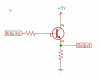
I've been using the below circuit to switch +5V on and off. For the -5V I'm guessing I can't just replace the +5 with -5?
 

Attachments

  • Screenshot from 2019-04-08 08-30-26.png
    Screenshot from 2019-04-08 08-30-26.png
    6.5 KB · Views: 223
That's a VERY poor way to do it, and you lose at least 0.7V - you should use a PNP transistor to switch the +ve rail (output from collector) and an NPN to switch the -ve rail. Depending on exact requirements, you may need two transistors to do it.
 
Why not switch the 5V supply to the ICL7660 with a PNP transistor or get a -5V converter with an enable pin?

Mike.
 
Why not switch the 5V supply to the ICL7660 with a PNP transistor or get a -5V converter with an enable pin?

Mike.
Would make a very ragged edge...

shf.png
 
Would make a very ragged edge...

View attachment 117562

I've no idea what your circuit is all about?, Pommie's idea of simply switching the +5V to the converter chip with a PNP transistor seems a good one.

However, is a fast response time even required? - but I don't see as your simulation shows anything?, why (and how?) are you feeding it a very slow analogue input, rather than a fast digital one?.
 
As we don't know what the -5V is used for the rise/fall times are irrelevant.

Mike.
 
...
However, is a fast response time even required? - but I don't see as your simulation shows anything?, why (and how?) are you feeding it a very slow analogue input, rather than a fast digital one?.
To prove that the switching point is at about the mid point of the Arduino Port Pin Swing.
ls.png


Why the antagonistic attitude?
 
Below is another way to switch -5V using two PNP's:
Note that the logic is inverted -- 0V in is -5V out.

1554745322836.png
 
Why the antagonistic attitude?

Not antagonistic, just that I didn't (and still don't) see the point?.

And as I also mentioned, Pommie's suggestion of switching the +5V to the converter seems by far the best option, and requires considerably less parts than either your or crutshow's examples.
 
As we don't know what the -5V is used for the rise/fall times are irrelevant.
My experience says otherwise. The OP doesn't know the questions to ask, or even that it might matter...
 
I think it's EXTREMELY likely that it doesn't matter, it would be pretty difficult to design something where it DID matter.
The OP specified he was switching -5V to an IC. Suppose this is some sort of programming pulse.
 
I assumed the -5 was a power rail and the op wanted to save power or reset the chip. Maybe we shouldn't assume.

Mike.
 
I see nothing antagonistic about Nigel's posts. Perhaps you're looking for a negative tone, so that's how you're reading them?
Don't think so.
Mike saw it and I saw it, but if you don't, that's fine.
 
Difference of opinions is how we learn.... Nigel can be a little harsh sometimes, but antagonistic is a little strong... All the senior members above have extremely good input to these threads... All we can do is give the TS ( OP ) our views, even if they are a little controversial... The TS may think that MikeMl's solution will work for him..
 
Almost forgot about this thread. Thanks for all the replies guys. I'm using the -5V on a old RAM Chip (4116) and the Arduino will run a memory test (and turn the -5V on and off)

Pommie is spot on, the solution is right there. Why didn't I see that :)I'm using a ICL7660 anyway to generate the -5V. I'll use a PNP to turn the voltage on/off to the ICL and then just add a delay on the Arduino code so the -5V can setting before I start testing.
 
Status
Not open for further replies.

Latest threads

New Articles From Microcontroller Tips

Back
Top