Continue to Site

Welcome to our site!

Electro Tech is an online community (with over 170,000 members) who enjoy talking about and building electronic circuits, projects and gadgets. To participate you need to register. Registration is free. Click here to register now.

  • Welcome to our site! Electro Tech is an online community (with over 170,000 members) who enjoy talking about and building electronic circuits, projects and gadgets. To participate you need to register. Registration is free. Click here to register now.

Using a photo sensor with pic

Status
Not open for further replies.

MrDEB

Well-Known Member
Presently I have a 2n2222 controlled by a PIR that takes an input LOW thus triggering the program.
Wondering If I could just use the ADC input with the Cds or photortransistor in series with a couple of resistor for a voltage divider. When light hits the sensor it shuts off the PIR input.
If I can get PAINT to be able to save a png file then I would post a schematic.
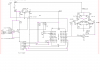
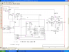
Will post an old schematic
here Q9 takes RB0 LOW but thinking of configuring a way to use similar to Q10 bt add another resistor to ground in series w/ photo sensor.
Then using ADC
WHILE TRUE portx <3 then port Y is enabled?
something along those lines. Just thinking out loud while tryiong to learn EAGLE pcb using the tutorial from sparkfun. Where is 1xFRAME-LETTER??
 

Attachments

  • critter combo6_21_10.PNG
    critter combo6_21_10.PNG
    37.9 KB · Views: 312
enabling a port based on different port

Got PAINT.NET working now to configure ADC to control port RB0 so in daylight the PIR is disabled. By adjusting R10 (need a pot instead) then adjust to daylight.
proposed code using swordfish but need to see if Swordfish has enable?
open for suggestions
 

Attachments

  • critter 6_290_10.png
    critter 6_290_10.png
    72.7 KB · Views: 196
MrDEB I can't open the attachment
I'm not a pro @ this stuff . But I have done what your asking. Not with swordfish but Pic basic Pro and assembly I just hook up the photocell as a voltage divider (I add a pot) for my use I leave the PIR active and depending on dip switch settings and the adc conversion it either does something (turn on camera, turn on light,etc) or jumps to delay. Because my stuff runs off batteries I use a output pin to power the photocell/voltage divider and turn the output off and on as needed.

maybe this will help not hurt you OR maybe some of the pro's will chime in
chow

LDR=1 'POWER UP LIGHT SENSOR
Pause 20
ADCIN 0,NIGHT 'READ AN1 & STORE IN NIGHT VAR
PAUSE 250
IF NIGHT=<550 Then GOTO DELAY ' IT'S DAY in night only mode

Pause 25
LDR=0 'power down light sensor

goto somewere or do what ever
 
Got it figured out Thanks

Using Swordfish to program PIC
here is basically what I am doing.
It works on breadboard
Now to try and see if when A) is high then B3 is enabled
Code:
Device = 18F1320
Clock = 8 // 8MHz clock
Config OSC = INTIO2, WDT = OFF, LVP = OFF 
Include "ADC.bas"                   // Include the ADC.bas library
 
Dim LED As PORTC.0                  // Declare the LED pin

//**********************************************
                 // sample ADC pin 1 input
//*********************************************** 
 
Function Get_ADC_Sample() As Word   // Function to grab the ADC sample
 
          result = ADC.Read(0)      // Grab an ADC sample from channel 0
           result = result * 2      // Scale the answer up by a factor of 2
 
End Function
 
 
OSCCON = %01110110                 // Setup the internal OSC for 8Mhz
 
Input(PORTA.0)                     // Make AN0 an inputpin 1

//********************************************************************
           // Create an infinate loop

//******************************************************************** 

While True                        
                        
    
    If (Get_ADC_Sample)<=512 
    Then Low (led0)
EndIf
    
    If (Get_ADC_Sample) > 512 
    Then Toggle (led0)             // Make the LED pin High
EndIf 
Wend
 
Status
Not open for further replies.

Latest threads

Back
Top