Continue to Site

Welcome to our site!

Electro Tech is an online community (with over 170,000 members) who enjoy talking about and building electronic circuits, projects and gadgets. To participate you need to register. Registration is free. Click here to register now.

  • Welcome to our site! Electro Tech is an online community (with over 170,000 members) who enjoy talking about and building electronic circuits, projects and gadgets. To participate you need to register. Registration is free. Click here to register now.

Using a FET instead of a Relay

Status
Not open for further replies.

Cobalt60

New Member
Can someone please tell me how I would go about replacing the Relay in the attached schematic w/ a FET?

Thanks

-Chris P
 

Attachments

  • fet.jpg
    fet.jpg
    228.6 KB · Views: 423
Well, since when the relay closes, it shorts the 15V supply to ground, I wouldn't. :D
 
Well, since when the relay closes, it shorts the 15V supply to ground, I wouldn't. :D

What is the load?
 
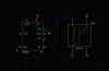
Its a Solenoid designed to run on 9V, but I am planning 7.4V. Resistance is 0.7ohms, so, I think w/ a fully charged battery it will pull over 11A. The 555 timer is there to precisely control the duration of power applied to the solenoid.

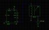
And just to upload a more accurate schematic with the load shown, here it is. The symbol is for a motor, but Im really driving a solenoid.
 

Attachments

  • fet2.jpg
    fet2.jpg
    195.3 KB · Views: 316
Do you know what a snubber is? Are you trying to run the 555 on the same power supply as runs the solenoid? What triggers the 555?
 
Do you know what a snubber is?

No.

Are you trying to run the 555 on the same power supply as runs the solenoid?

Yes, although Im not entirely opposed to running separate supplies. Id prefer a single power supply though.

What triggers the 555?

Just a regular switch. The 555 is in monostable mode so that no matter how long the switch is pressed, power is only applied for a predetermined duration.
 
Last edited:
Ok. Folks have tried to use the 555 (and ucontrollers) to pulse highly inductive loads (with an intervening NPN or NFET transistor), and have complained that the inductive spike generated as the 555 turns off causes the 555 to retrigger (or reset the uController). If you are willing to give it a go with a common power supply, then it is essential that there be 10uF and 100nF bypass capacitors (in parallel) on the Vdd to Vss pins of the 555 (with almost zero lead length), and a 100nF on the unused VCO input to Vss. There also must be a diode snubber (or at least an R-C snubber) across the solenoid coil. There was a long-running "Snubber" thread on this web site a few months ago.

Basically, you will need a T0-220 style NFET mounted on a heatsink, with a gate threshold of <4V, an max Id of ~25A, Vds of > 50V, Ron of <0.1Ω. You will ground the source (battery negative). The drain goes to the solenoid/anode of the snubber. The other end of the solenoid/cathode of the snubber goes to the battery positive. Place a 10Ω, non-inductive resistor between pin 3 of the 555 and the NFET gate.

If you experience retriggering after bypassing and adding the snubber, then the next suggestion is to use a separate battery for the 555, and use an opto-isolator to keep the 555 battery totally isolated from the solenoid battery. (No common ground between the two).
 
Last edited:
I just changed out 3 relays on my off highway vehicle with P FETs (irf4905)(as the Contacts) and used an N FEFT (IRFD014PBF) as the coil (sort of) because the Polarity required P FETs and the gate voltage applied required the use of N FETs. Attached is the schematics for before and after with the worked on part being in the blue box. Some of the relays were controlled on the high side and some on the low side and some on both sides. Any way, take a look and see what you think.
Kinarfi
**broken link removed** **broken link removed**
 
Status
Not open for further replies.

Latest threads

Back
Top