Hello all,
I'm a PhD Physiology student from Manchester University and have an idea for measuring tissue density using a laser, a light dependent resistor and a 741 op amp.
It is probably worth saying that although I am fairly familiar with electronics, I am by no means competent....and basically I would be very greatful to know your thoughts on this idea and whether it would work....
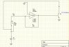
In essense i intend to shine a 1mW laser through very thin sections of tissue on to an LDR. If tissue density decreases, more light will get through and therefore the LDR resistance will decrease. I want to amplify this change in resistance/current somehow and and am thinking of a 741 op amp.
The output of the 741 would then go into a computer via Powerlab which would record the fluctuating output.
The laser and LDR will remain in a fixed position and the tissue would be moved within the beam. Any change in tissue density within the sample should I guess result in a fluctuating current input into the 741
I have a few questions:
1)Would an LDR between the +ve rail and 741 input work?
2)Will the output from the 741 directly correlate with the input?
3)Will this work?!
Sorry if I sound a bit thick, cheers in advance.
I'm a PhD Physiology student from Manchester University and have an idea for measuring tissue density using a laser, a light dependent resistor and a 741 op amp.
It is probably worth saying that although I am fairly familiar with electronics, I am by no means competent....and basically I would be very greatful to know your thoughts on this idea and whether it would work....
In essense i intend to shine a 1mW laser through very thin sections of tissue on to an LDR. If tissue density decreases, more light will get through and therefore the LDR resistance will decrease. I want to amplify this change in resistance/current somehow and and am thinking of a 741 op amp.
The output of the 741 would then go into a computer via Powerlab which would record the fluctuating output.
The laser and LDR will remain in a fixed position and the tissue would be moved within the beam. Any change in tissue density within the sample should I guess result in a fluctuating current input into the 741
I have a few questions:
1)Would an LDR between the +ve rail and 741 input work?
2)Will the output from the 741 directly correlate with the input?
3)Will this work?!
Sorry if I sound a bit thick, cheers in advance.