Continue to Site

Welcome to our site!

Electro Tech is an online community (with over 170,000 members) who enjoy talking about and building electronic circuits, projects and gadgets. To participate you need to register. Registration is free. Click here to register now.

  • Welcome to our site! Electro Tech is an online community (with over 170,000 members) who enjoy talking about and building electronic circuits, projects and gadgets. To participate you need to register. Registration is free. Click here to register now.

Using 1kHz PWM to switch 3-12v, 1Amp - MOSFET, BJT, relay?

Status
Not open for further replies.

astronomerroyal

New Member
I'm embarrassed to say that I've had this very elementary problem for weeks now, without finding the solution by my self.

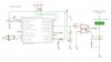
I have a micrcontroller device producing a 1kHz PWM signal that I would like to use to switch a power circuit on and off*. This is primarily being used as an LED-dimmer device. The 1kHZ PWM apparently precludes the use of a mechanical relay. All I want is something that can be switched on/off at 1kHz. Energy efficiency is important also as it will be running on AA NiMHs.

* Currently the microcontroller is 5V, but soon will be moving to 3v device. The power circuit consists of one or more (in parallel) 1W LEDs each running at 0.35A and ~3.6v (3xNiMH AA). A max current of 1A would be fine.

Is the answer obvious? Any specific devices spring to mind? As always, your help is greatly appreciated.

Here's what I've being toying with...


MOSFET:
More complicated operation than I expected, since efficacy depends on gate-source and drain-source voltages. In my case these are very/too small (both <5v) for the random sample of power MOSFETs I've looked at.

Power transistor:
Simpler to understand, but consumes current at base and incurs C-E voltage drop, unlike MOSFET. I can live with these, but I want this device to be as energy efficient as possible.

Solid-state relay:
A mystery to me. Some of these seem to be beefed up optocouplers.
 

Attachments

  • PWM_switching_options.jpg
    PWM_switching_options.jpg
    70.9 KB · Views: 2,898
Last edited:
About 10% of the posts in these Forums deal with this question. Have you done a little searching/reading before we rehash it yet again?

Hint: start by reading the VoL and VoH specs for a port pin on your PIC Data Sheet when it is operated at a Vss of 3V. Then consider how much current the port pin can source when high, and how much it can sink while low. Then look up the data sheets for some mid power NPN and NFets to see how much current/voltage it takes to turn them on fully.
 
Last edited:
About 10% of the posts in these Forums deal with this question. Have you done a little searching/reading before we rehash it yet again?

Oh dear, the dreaded line. Sorry, I hoped my threads were of acceptable quality. Yes I searched widely, although I may not have a talent or it. My opening line alluded to thoughtful readings of Paul Scherz's book and posts such as these,

https://www.electro-tech-online.com/threads/new-guy-here-with-a-mosfet-question-as-in-recommend-me-one.93485/

https://www.electro-tech-online.com/threads/controlling-power-to-a-load-using-transistor-or-otherwise.94192/

None of which equates to experience. I posted schematics for 3 possible approaches. What I was hoping for is something incisive, such as 'Sir, a low Vgs MOSFET such as ZXMN6A07F is perfect, albeit surface mount only. However, for a range of power voltages, a BJT may be a better guarantee of versatility - at the cost of energy wastage. A solid-state relay is best is you need isolation and large power transmission, but is generally more expensive and therefore overkill for your project.'

... or a link to a previous hashing that is pertinent to my scenario.

Thanks, truly - I don't take for granted the infinite patience of people like Nigel Goodwin, Eric Gibbs et. al. ...
AR.
 
What voltage / power source are you using to power the 1W LEDs? What is their forward voltage?

Hi, I was planning on using 3 (possibly 4 if necessary) AA NiMH for the LED power supply. The LEDs are ('3.7v typical driving voltage')

**broken link removed**

each with an efficient 350mA regulator ('Recommended input voltage range: 3.6V~4.5V')
**broken link removed**

I have the LED+Driver up and running - it seems quite an efficient setup. Just want to switch it on and off at 1kHz without compromising this efficiency.

Keen to hear your thoughts.
 
I don't see a schematic for those drivers but they are probably similar to the Joule Thief design and will only work well with a DC source.
 
I don't see a schematic for those drivers but they are probably similar to the Joule Thief design and will only work well with a DC source.

Sorry, I forgot to add that the driver's actually just a single component (ignoring the protection diode) - the AMC7135 - the rest is just empty PCB.

I don't know its history but it's a brilliant little thing,
**broken link removed**

Datasheet doesn't mention AC at all. While the subject is discussed on flashlight forums, I don't know if it's okay with 1kHz PWM. Even if I don't use the AMC7135 the basic switching issue still remains.

EDIT: I found that I have some ULN2003A Darlington arrays. Presumably this would be a usable solution along the BJT line - in case no MOSFET solution is forthcoming. I've never used a MOSFET in a circuit, and it would be nice to try them as they sound potentially ideal.
 
Last edited:
Hi, I was planning on using 3 (possibly 4 if necessary) AA NiMH for the LED power supply. The LEDs are ('3.7v typical driving voltage')
...
I have the LED+Driver up and running - it seems quite an efficient setup. Just want to switch it on and off at 1kHz without compromising this efficiency.

Do you want to switch the high side (between battery + and the + input to the driver) or the low side (- input of the driver to ground). Is your PIC running on battery + ?
 
Do you want to switch the high side (between battery + and the + input to the driver) or the low side (- input of the driver to ground). Is your PIC running on battery + ?

1) PIC is running off a separate set of 4AA NiMHs. Common ground. Originally I planned on having the Logic and Power circuits (opto)isolated from one another. The original concept is shown in attachment. I'd hoped it would be a general purpose PWM switching device, but apparently that was ambitious ...

2) I'm happy to switch it either way, high- or low-side. The driver IC (AMC7135) is of the sink variety, I don't know if that's important.
 

Attachments

  • PWM_switching_original_concept.jpg
    PWM_switching_original_concept.jpg
    139.3 KB · Views: 2,858
Last edited:
I was wondering if anyone could clarify whether this AQV2121 solid-state relay would be suitable for switching my 3.6V LED (+ v. low-dropout constant current driver) from 3.6 or 4.8volt supply.

It says it can switch 500mA DC loads, has Ron~1 Ohm, and has an '...extremely low
closed-circuit offset voltage to enable control of low-level analog signals ...', which presumably includes my case ( it doesn't seem to state the lowest voltage it can switch). Right now I'm not concerned with switching speed - just want a basic switch.

**broken link removed**

Perhaps even better, though not providing isolation, is this N-MOSFET

MLP1N06CL which explicitly states that it is good for interfacing directly with microcontrollers.
 
Last edited:
a typical pic can output 20ma on an given pin so it should have no problem directly driving a 500ma load through a bjt (of reasonable beta) or a mosfet.

the advantage with bjt for this application is their low Vbe so you can saturate those devices even if you go to a 3v device.

the disadvantage of a bjt is that it has to have big enough of current out of the PIC - not a problem here, and they do suffer from 2ndary breakdown so be careful reading the datasheet for SoA.

the advantage of using a mosfet is that a) they are very easy to drive so even if you move to a 2ma / 4ma device later, your driver section remains intact; b) they are ohmic device once they are on; and c) they are cheap and robust.

however, you have to use a logic level mosfet to be sure that it operates on 3v rails.

I would go with a bjt here because I have lots of them.
 
Sorry, I forgot to add that the driver's actually just a single component (ignoring the protection diode) - the AMC7135 - the rest is just empty PCB.

I don't know its history but it's a brilliant little thing,
**broken link removed**

Datasheet doesn't mention AC at all. While the subject is discussed on flashlight forums, I don't know if it's okay with 1kHz PWM. Even if I don't use the AMC7135 the basic switching issue still remains.

it doesn't take a control signal, analog or digital. so it wouldn't be of any use to you.

if you want, you can use many smps chips and configure them into a led (constant current) driver. ON Semi has quite a few of them, in either step down or step up mode, in sot23 packaging that take digital or analog controls.


EDIT: I found that I have some ULN2003A Darlington arrays. Presumably this would be a usable solution along the BJT line - in case no MOSFET solution is forthcoming. I've never used a MOSFET in a circuit, and it would be nice to try them as they sound potentially ideal.

ULN2003 would work, but a simple to220 bjt would be far easier.

using a mosfet isn't that much different from using a bjt.
 
LEDs can be easily burned out if overdriven by large current. so I think it makes sense that you use some form of LED drivers to avoid that, or to use the mcu to monitor drive current and adjust the pwm duty cycle accordingly.
 
Millwood & SpeakerGuy79 - this is *exactly* the info I was after. Thanks for your time.

Now I better see where I stand. I finally see how many options I have. I just didn't know what I was looking for, or how to search for them properly.

That NTJS3157N looks like an ideal choice for switching.
 
Status
Not open for further replies.

Latest threads

New Articles From Microcontroller Tips

Back
Top