Continue to Site

Welcome to our site!

Electro Tech is an online community (with over 170,000 members) who enjoy talking about and building electronic circuits, projects and gadgets. To participate you need to register. Registration is free. Click here to register now.

  • Welcome to our site! Electro Tech is an online community (with over 170,000 members) who enjoy talking about and building electronic circuits, projects and gadgets. To participate you need to register. Registration is free. Click here to register now.

undesired ripple in a simple PWM circuit

Status
Not open for further replies.

Quank

New Member
Hi everybody!
I made a circuit for generating an "square wave" signal with adjustable frequency and Duty Cycle. For me is enought to be able to regulate Duty Cycle manually adjusting some potentiometers. I call this a PWM (I know it is no exactly one).
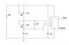
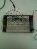
I attatch you the circuit schemattics (Esquema12.png), a foto with the protoboard (Foto1.JPG).

Vin: 5 V
C1: 2.2nF
C2: 0.01 uF
R1: Potentiometer 10K
R2: Potentiometer 10K
D1: FS 1N4934 (max trr 150 ns)

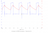
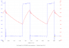
The circuit is adjusted to produce a 100 KHz frequency and a 30% Duty Cycle.

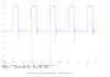
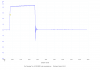
I attatch some captures of the osciloscope (Picoscope 2203): (Esquema13.png to Esquema17.png)
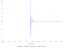
My problem is that I've discovered a little ripple in the output (as you can see in Esquema15.png). I think that's produced for the oscilation in the capacitor (as you can see in Esquema17.png).
As you can see, the problem is only present in the fall time, because the rise time is perfect! Intuitively, the problem occurs when the threshold input makes the output low, but I don't know how to eliminate this oscilation!
Can anybody help me?
Thank you in advance

quank
 

Attachments

  • Esquema12.png
    Esquema12.png
    111.4 KB · Views: 92
  • Foto1.JPG
    Foto1.JPG
    95.5 KB · Views: 86
  • Esquema13.png
    Esquema13.png
    60.4 KB · Views: 90
  • Esquema14.png
    Esquema14.png
    50.2 KB · Views: 83
  • Esquema15.png
    Esquema15.png
    50.8 KB · Views: 89
  • Esquema16.png
    Esquema16.png
    58.4 KB · Views: 92
  • Esquema17.png
    Esquema17.png
    62.3 KB · Views: 89
When the 555 starts to discharges C1, the stray capacitances on the discharge pin are discharged very quickly. The current is very large, so there is ringing in all the stray inductances as that current starts.
 
do you have acsess to a analog scope kinda looks like a lot of jitter is happening or somthing with the sampling.
I personaly haven't seen any ringing that bad on 555's with my 40mhz analog scope.
Just wondering as I don't have any experience with the Picoscope products.

jer :)
 
Each wire on the breadboard is an inductor that produces voltage spikes.
Each connector strip and wire on the beadboard has capacitance to other connector strips and wires that add to the inductance of the wiring and make ringing LC tuned circuits.

Hint: Get rid of the breadboard.
 
He could also try shortening the jumper length a bit. He may also try to add an output filter with a 1k resistor and a 10nF cap to smooth the signal out a bit. I'm not 100% on how that would affect the circuit, I'm just throwing some numbers out there.
 
I think that the "ripple" could be due to the way the circuit is built and how you are measuring it.
(A better word for the "ripple" would be "ringing". That is the usual expression for oscillation following a sharp change in a waveform).

You are running the circuit at quite a high frequency (100khz), which means that the ringing frequency will be several Mhz.
The circuit is built on a breadboard which itself is not good at high frequencies.
There are long wires connecting the various parts of the circuit, the long wires will have inductance.

The connection to the picoscope appears to be a simple twin wire cable rather than a low capacitance high impedance scope probe.
The twin cable will have significant amounts of capacitance, and inductance.

So, if you want perfect edges on your square waves, build the circuit on a low impedance ground plane with short connections, and make the measurements using a divider probe (divide by 10) for the scope.

JimB
 
Hi. I'm kind of used to test circuits on bradboards. The wiring itself is awfull and it's a great chance that fixing those will be the solution. See my atached figure.
 

Attachments

  • Breadboard_bad.png
    Breadboard_bad.png
    40 KB · Views: 79
  • Breadboard_good.png
    Breadboard_good.png
    30.3 KB · Views: 83
I have built such circuits like that and more worse of a ratsnest than you can imagine,still have not encountered such ringing,except possibly when using just a piece of cable that was uncompensated.
Try using a regular scope probe and see if that will help,if you don't have one there are very easy to make.
I do remember trying to use just a piece of cable once and the results where very bad for square waves since then I have always used my probe.
It was a very long time ago so I don't remember the details.
I have used just a piece wire from the BNC on the scope with good results but this is more susceptible to external RF noise but I have not had ringing issues using this method.

just a few thoughts. jer :)
 
You might also want to add a decoupling capacitor from Vcc to ground close to the IC.
 
I have built such circuits like that and more worse of a ratsnest than you can imagine,still have not encountered such ringing,except possibly when using just a piece of cable that was uncompensated.
I have. And also I have some storys with rat nests. In at least two particular cases that I remember, straighten up the wiring did solve the ringing problem.
 
Thank you everybody for your answers. They are focused in perfectioning circuit construction. I will do it.
Don't you think is a possible problem of the trr of the diode? Maybe a capacitor in parallel with the diode?
Thanks..
Quank
 
Thank you!!!
I've ordered two new probes and I'm reconstructing my circuit. I think is the best advice to begin with this!!
For me is a closed question!
Bye
 
Status
Not open for further replies.

Latest threads

New Articles From Microcontroller Tips

Back
Top