Continue to Site

Welcome to our site!

Electro Tech is an online community (with over 170,000 members) who enjoy talking about and building electronic circuits, projects and gadgets. To participate you need to register. Registration is free. Click here to register now.

  • Welcome to our site! Electro Tech is an online community (with over 170,000 members) who enjoy talking about and building electronic circuits, projects and gadgets. To participate you need to register. Registration is free. Click here to register now.

Understanding the design of diode clampers

Status
Not open for further replies.
Hello everyone.
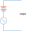
I have a little difficulty in understanding the design of diode clampers. Basically the purpose of clampers is to add some DC value to the AC signal. So why dont we add a battery directly in series with the AC source. The output we get will be AC + DC. So why do we use diodes and capacitors etc. Am I missing something. Really hope to receive help.
Best Regards
LK
 
Your post makes little sense, you need to be far more specific what you're talking about - but adding an extra battery for no reason sounds pretty pointless.

Generally a 'diode clamp' would be on inputs (such as PIC's, where they are built-in), and prevent the inputs exceeding the supply rails (or at least by more than 0.7V), no use for a battery there?.
 
Hi Nigel,
Thanks for the reply. Let me try to explain. I was starting to learn about diode clippers, and in reference books it is given that clampers are used to shift the DC level of signals. The design of clamper is also given, which i have uploaded here under the title "diode clamper". The circuit shifts the DC value of signal at approximately Vp - peak value of signal. Now what I dont understand this is why do we use diodes and capacitor. If we want to raise the DC value, then why cant we add a battery of desired voltage in series with the source, as shown in the uploaded file under the title "using a battery to shift DC level". I guess that would be easier as we can achieve the goal with just one component(battery) rather than using diodes and capacitors. What do you say Nigel?
Thanks in advance for any help
Best regards
LK
 

Attachments

  • diode clamper.jpg
    diode clamper.jpg
    6.9 KB · Views: 446
  • using a battery to shift DC level.png
    using a battery to shift DC level.png
    3 KB · Views: 211
That is a positive unbiased clamper circuit,
Your output voltage would be in that case 2Vp.
In short, the diode only allows current to flow one way, so during the positive cycle the diode will not conduct, it also prevents it from exceeding the reference value and the capacitor is used to store the DC offset, essentially acting as a voltage doubler.
 
Hi Nigel,
Thanks for the reply. Let me try to explain. I was starting to learn about diode clippers, and in reference books it is given that clampers are used to shift the DC level of signals. The design of clamper is also given, which i have uploaded here under the title "diode clamper". The circuit shifts the DC value of signal at approximately Vp - peak value of signal. Now what I dont understand this is why do we use diodes and capacitor. If we want to raise the DC value, then why cant we add a battery of desired voltage in series with the source, as shown in the uploaded file under the title "using a battery to shift DC level". I guess that would be easier as we can achieve the goal with just one component(battery) rather than using diodes and capacitors. What do you say Nigel?

Not 'easier' at all, it's greatly inconvenient having to repeatedly change the battery, and you also have to arrange a switch for it to prevent it discharging when the circuit isn't in use. Obviously it's also VERY much more expansive.

I would suggest a better name (and the correct one?) would be 'DC restoration', and a similar circuit was used (and called that) in TV's for many years - radio signals are AC only, so the TV set needs to restore the DC component of the received picture signal (no need to for audio, which is AC only).
 
An isolated battery would add a bulky, expensive component that needs to be periodically replaced, so they are seldom used unless there's no other choice. Using a minimum number of components to do a task is not always the best, or even cheapest way.
 
Thank you very much Nigel and Crutschow for your replies.
I now have the thorough understanding of why a battery is not preferred over the circuit consisting of diodes and capacitors. Just a little confusion though :), I would be very glad if you could clarify the doubt. In biased clampers, there is a battery connected in series with the diode. Is the battery actually used in any practical circuits? Or some resistive voltage divider network is used in place of battery to achieve the desired voltage.
Thanks in advance again for any help
Regards
LK
 
You don't use batteries for any such purposes, they are expensive, short lived, require regular changing, and offer no advantages over doing it the normal way.
 
Where?, and why? - not as far as I'm aware - I suppose the Z-input is a possibility?, but few scopes have them, and it's an extremely rare feature to use.
Z drive is the reason.
Note pages 52,53 here:
https://www.hellspark.com/dm/ebench/tools/Analog_Oscilliscope/tektronix_2213_service.pdf

The DC Restorer circuit produces the crt control-grid bias and couples both DC and low-frequency components of the Ζ-Axis Amplifier output to the crt control grid. Direct coupling of the Ζ -Axis Amplifier out put to the crt control grid is not employed due to the high potential differences involved.
 
Status
Not open for further replies.

Latest threads

Back
Top