anand.usic
New Member
Hello,
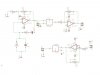
I am trying to construct one ultrasonic distance measurement circuit which uses 40KHz signal input. I used wein bridge oscillator in this circuit and AND gate for giving the input. In one terminal of the input the oscillator is connected and the other terminal for user control and the output of the and gate is given to the sensor.
In the reverse action the output of the sensor is amplified and taken for processing.
My question is whether the circuit will work or not.
if not please guide me in this regard. the circuit is attached.
")
