Continue to Site

Welcome to our site!

Electro Tech is an online community (with over 170,000 members) who enjoy talking about and building electronic circuits, projects and gadgets. To participate you need to register. Registration is free. Click here to register now.

  • Welcome to our site! Electro Tech is an online community (with over 170,000 members) who enjoy talking about and building electronic circuits, projects and gadgets. To participate you need to register. Registration is free. Click here to register now.

UC3842 based SMPS mosfet probelm

Status
Not open for further replies.

saqib_ee

New Member
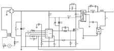
i made 220V AC to 12V DC 5A SMPS based on UC3842 using forward converter. schematic attached. supply's output voltage is ok and on no load (except indication led) pwm duty cycle is 1.1% with no mosfet heating (IRF740), but when loaded with even a little load of < 500mA, mosfet heats up although the primary side current is very less (<150mA) while the IRF740 is rated for 10A current. is it the snubber problem ? i first used 50K snubber resistance based on a design i found on the web and capacitance of 1nF (RCD snubber) later replaced 50k with 5K. but using less snubber resistance is burning the UC3842 chip, current sense resistance of 0.22R and 1K resistor on current sense line going to pin 3. what am i missing in this design? is it because i am directly driving mosfet from uc3842 output? or is it really the snubber problem. (F sw = 80kHz)
 

Attachments

  • 3842.jpg
    3842.jpg
    135.4 KB · Views: 343
1- The US3842 was not designed for "forward" but "flyback".
2- I cannot see the phase of the primary. The dot is in the center of the winding.
3- Cannot work without an output capacitor.
4- Seems odd that the output has a LC filter like a Forward but the Aux supply looks like a Flyback output.
 
ignore the dots. and its just a schematic drawing mistake. output does have a capacitor. i am confused about the exact concept of flyback and forward topologies. why uc3842 cant be used in this manner?
 
In the simplest possible terms:
  1. In a forward converter, the secondary is in phase with the primary.
  2. In a flyback converter, the secondary is 180° out of phase with the primary.
Each of these two alternatives have other requirements and implications.
 
In the simplest possible terms:
  1. In a forward converter, the secondary is in phase with the primary.
  2. In a flyback converter, the secondary is 180° out of phase with the primary.
Each of these two alternatives have other requirements and implications.
so in my shematic i used a transformer with output in phase and the aux supply whether out of phase or not it just need to supply 15v to the chip. when i turn on supply on no load i get 15v at the aux winding after diode.should it not work ?
 
so in my shematic i used a transformer with output in phase and the aux supply whether out of phase or not it just need to supply 15v to the chip. when i turn on supply on no load i get 15v at the aux winding after diode.should it not work ?
I'm not clear on the situation where you have multiple secondaries with opposite polarity windings. The reason I'm not sure about this is that secondary winding load impedances are reflected back to the primary.
 
Normally I would say the snubber is not a problem, but I need more information.
There are many different types of FR1 diodes. If you picked an "A" then you have killed the diode and that will cause MOSFET heating.
1659302257692.png


----------------------------
There is no part number for the Zener near the opto isolator.
 
The UC3842 is not recommended for controlling a forward converter in that it's duty cycle can go to 100%. Generally, single ended forward converters shouldn't be run higher than 50%.

A better choice would be the UC3844/45 versions of the same family, as they are internally limited to 50% max.
 
Normally I would say the snubber is not a problem, but I need more information.
There are many different types of FR1 diodes. If you picked an "A" then you have killed the diode and that will cause MOSFET heating.
View attachment 138041

----------------------------
There is no part number for the Zener near the opto isolator.
the diode is FR107 while is zener near opto is a 11v zener for 12 v output and i do get 12v output. the supply runs small DC gear motors fine. but duty cycle for such small loads (<1A) also reaches to more than 75% which was 1% on no load. i loaded these motors for 15 minutes with not much heating of mosfet but when i load anything more than that (car lamp etc) then mosfet heats up a lot and supply is noisy although everything including mosfet is rated for higher loads.this all happens when snubber resistance is 50k. on small resistance (<5k), sense resistance 0.2R, 1k resistor on sense line and sometimes chip also burns.
 
I'm not clear on the situation where you have multiple secondaries with opposite polarity windings. The reason I'm not sure about this is that secondary winding load impedances are reflected back to the primary.
if you were to make a simple forward or flyback convertor using any chip that also need aux supply then what would your transformer be like?
 
The UC3842 is not recommended for controlling a forward converter in that it's duty cycle can go to 100%. Generally, single ended forward converters shouldn't be run higher than 50%.

A better choice would be the UC3844/45 versions of the same family, as they are internally limited to 50% max.
i do agree because duty cycle is part of the problem here as it reaches more than 75% in my case even for small output loads(<1A) which i am not sure why. but at duty of 75% and 80KHz switching, primary current is still in few mAmps and still heating the mosfet i am not sure why either.
 
I expect that the circuit is actually operating as a flyback supply, and not a forward converter.

In order to help us help you, please do the following:
  • Redraw the schematic to accurately match what you've actually built. Including the correct phasing of the transformer. Please put reference designators by every component. Include pin numbers for all of the transformer connections.
  • Provide the construction details of the transformer, including inductance and number of turns of the primary. Also the number of turns for the Aux and secondary windings.
  • I'm assuming that you have an oscilloscope. Hopefully it has at least two channels as it will be important to view two signals at the same time to see the relative timing.
  • Very Important!! You'll need an isolation transformer to separate the primary side circuitry from the AC line. This is so that you can probe primary points without blowing the supply and/or the scope up.
  • And remember, there are hazardous voltages present in the circuit. Be Very Careful.
 
Where did you copy this design from? Please give us a picture of the transformer and inductor. Include number of turns and inductance if you have it.
 
Status
Not open for further replies.

Latest threads

New Articles From Microcontroller Tips

Back
Top