Continue to Site

Welcome to our site!

Electro Tech is an online community (with over 170,000 members) who enjoy talking about and building electronic circuits, projects and gadgets. To participate you need to register. Registration is free. Click here to register now.

  • Welcome to our site! Electro Tech is an online community (with over 170,000 members) who enjoy talking about and building electronic circuits, projects and gadgets. To participate you need to register. Registration is free. Click here to register now.
Status
Not open for further replies.

aksnis

New Member
Hello
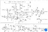
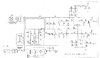
I am trying to repair a smps power supply based on UC3825A
Problem is the resistor R49 & R34 get burst as soon as i start the smps
I am not able to find out the issue
SYS_ECON is a 0-5v given from MCU desired by user to control 0-180v smps output
 

Attachments

  • 6A7780EC-A374-48B4-9848-C73B19256D70.jpeg
    6A7780EC-A374-48B4-9848-C73B19256D70.jpeg
    730.8 KB · Views: 287
  • 62879F21-9BFA-43FF-8913-EAB2D6A3E512.jpeg
    62879F21-9BFA-43FF-8913-EAB2D6A3E512.jpeg
    535.7 KB · Views: 292
Measure R35. If R49 and R34 are being damaged, I can't see any reason other than R35 being shorted, or at least much lower value than the 100 kOhms that it should be.

As it's a switch mode power supply, that may not be the only failure. If R35 is shorted, U7 may be damaged. R52 is doing a very similar job to R35, and is exactly the same specification, so it may have failed as well.

How are you monitoring the main output voltage?
 
Measure R35. If R49 and R34 are being damaged, I can't see any reason other than R35 being shorted, or at least much lower value than the 100 kOhms that it should be.

As it's a switch mode power supply, that may not be the only failure. If R35 is shorted, U7 may be damaged. R52 is doing a very similar job to R35, and is exactly the same specification, so it may have failed as well.

It would be VERY, VERY rare for even a remotely modern resistor to go short or low in value - the odd ones which used to were really old types (used way back in valve equipment).

From the schematic there seems nothing that could cause R49 and R34 to repeatedly fail - my main thoughts would be a PCB fault, or some kind of contamination (liquid spilt on the board).
 
I agree with what Nigel said.

R34 is 1/1000 of the value of R35, so the expectation would be 1/1000 of the heat generated. So if R34 fail instantly, a lot of current is flowing that isn't flowing through a 100 kOhm resistor.

As failure of the resistor is unlikely, and you've tested its resistance, then it seems that there has to be an alternative current path that isn't shown on the circuit. That could be contamination from the test point between R34 and R35.

The output voltage has to be around 100 V, most of which will be across R35 in normal running. I would still be suspicious of that resistor because you have only tested it's value with a few volts when a multimeter is used. The resistor's insulation could have broken down, so that it's fine at a few volts, but arcs across at 100 V.

I recently had a SMPS blow when the common-mode choke shorted from one coil to another. There was some potting compound applied to the coils to keep them in place. There had been voids in the potting compound and I suspect that condensation had formed in the voids, leading to a path for mains voltage to break through on. Obviously it wouldn't be possible to spot that with an Ohmmeter. The voltage rating between the coils was fine for mains voltage, but the gap was only 2 mm or so, and that is comparable to the length of a 1/8 W resistor.

The ICs on this board date to the late 1990s, so I guess the board is over 20 years old. It might be worth testing R35 at 120 V or so, or just swapping it as a replacement is cheap. A resistor rated at 200 V is important here, and many 1/8 W resistors are rated to that voltage.
 
The equipment is very old its a medical equipment
Initially i replaced the components then again the new resistor burnt

The power supply is of an electrosurgical unit
Initially it does a self test during which the self test hangs and puffff!!!!!
Resistors gone
 

Attachments

  • E19CC1DB-5EB6-4340-9FAF-5DE190BA76D7.jpeg
    E19CC1DB-5EB6-4340-9FAF-5DE190BA76D7.jpeg
    143.3 KB · Views: 266
  • B5B66E83-82B1-4727-A15F-34B71691CCE9.jpeg
    B5B66E83-82B1-4727-A15F-34B71691CCE9.jpeg
    115.2 KB · Views: 256
My best guess is that there's been dendrite growth, or tin whiskers, or something else that has shorted R35.

I can't work out from the photo which end of R35 is supposed to be connected to which end of R34. There what looks like a blown track that used to run past the top end of R34 (top as in the end physically nearest TP16). The circuit shows TP16 connecting to R35 and R34 only. My first guess would be that the top ends of those resistors would be the ones connected to TP16, but it's not clear.

Have you got a photo from the other side of the board, of that part, or can you explain how R34 and R35 line up with the other photo?
 
Status
Not open for further replies.

Latest threads

New Articles From Microcontroller Tips

Back
Top