Continue to Site

Welcome to our site!

Electro Tech is an online community (with over 170,000 members) who enjoy talking about and building electronic circuits, projects and gadgets. To participate you need to register. Registration is free. Click here to register now.

  • Welcome to our site! Electro Tech is an online community (with over 170,000 members) who enjoy talking about and building electronic circuits, projects and gadgets. To participate you need to register. Registration is free. Click here to register now.

Two transistor LED flasher

Status
Not open for further replies.

zachtheterrible

Active Member
Hello, I would be GREATLY indebted to whoever can help me understand how the devil this little circuit works. ITS BEEN DRIVING ME NUTS!!!!!!!!!!!!
 

Attachments

  • led_flasher.gif
    led_flasher.gif
    3.7 KB · Views: 698
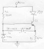
C1 charges through R2 and R1 until the charge is high enough to turn on Q1. This causes Q2 to turn on. The LED is now connected to +Vcc and GND through Q2 and R3, thus lighting the LED.

After this happens, C1 discharges through the base-emitter of Q1. This causes Q1 to turn off, which then switches Q2 off. Once Q2 is switched off, the LED doesn't light up. Then the cycle repeats as the capacitor charges.

R2 can be adjusted to speed or reduce the charge rate of C1, this allows the user to adjust the flashing rate because C1 governs the oscillations(On and off fucntions) of the transistors Q1 & Q2.

D1 prohibits current from flowing to GND before the current goes through R2, C1 and R3.

R3 protects the LED and Q2 from excessive current when Q2 is switched on by Q1.

I hope this makes sense.
 
Thank you SOO very much johnson, it was crystal clear. One last question is, why is the diode there, couldn't you just have no connection there, and it would do the same thing?
 
zachtheterrible said:
Thank you SOO very much johnson, it was crystal clear. One last question is, why is the diode there, couldn't you just have no connection there, and it would do the same thing?

The diode is there to prevent the first transistor blowing, as the circuit turns off the timing capacitor places too high a negative voltage on the base - this would blow the transistor. The diode reduces the negative voltage on the base to only 0.7V, which is well within the transistors specifications.
 
I now understand how the two transistor led flasher works, but why won't this circuit here work? I would imagine that it would work just as well, but I put it on a simulation and played around with the values of components, but it didn't work.
 

Attachments

  • 1_transistor_led_flasher__doesnt_work_.jpg
    1_transistor_led_flasher__doesnt_work_.jpg
    23.5 KB · Views: 625
Status
Not open for further replies.

Latest threads

New Articles From Microcontroller Tips

Back
Top