Continue to Site

Welcome to our site!

Electro Tech is an online community (with over 170,000 members) who enjoy talking about and building electronic circuits, projects and gadgets. To participate you need to register. Registration is free. Click here to register now.

  • Welcome to our site! Electro Tech is an online community (with over 170,000 members) who enjoy talking about and building electronic circuits, projects and gadgets. To participate you need to register. Registration is free. Click here to register now.

Two analogue signals - Highest wins

Status
Not open for further replies.

simdel96

New Member
Hi,

I'm not very good with electronics and all of this is new to me, so I was hoping that someone on here might be able to help me with a little project of mine.

I am working on an automotive application where there are two 0-5V signals generated. The ECU I'm using can only accept one signal so I need to create some sort of device that will compare both signals and only output the highest of the two.

I initially looked at using diodes, but it seems that there will be large a voltage drop, so the output signal will not be the same as the largest input. After a bit of searching on google and wikipedia I've come up with a first draft of something that might work. I've attached it below. (don't laugh!)

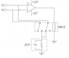
V1 and V2 are the input voltages from the sensors
Vo is the voltage as detected by the ECU. This should be equal to the largest of V1 and V2

The way I want this to work is that when V1 is greater than V2, the output from the comparator is 0 (0v). The relay remains in the same position as drawn, and therefore only V1 is connected to the ECU. When V2 is greater than V1, the output from the comparator is 1 (12V) which drives the relay and therefore only V2 is connected to the ECU.

I'm pretty certain that i'm missing something important so any help would be greatly appreciated.
 

Attachments

  • Analogue-comparator.JPG
    Analogue-comparator.JPG
    19.5 KB · Views: 165
Last edited:
Just a random thought...

As this switches, there will be a brief moment where there is no signal going to the ECU. This might result in an out of range error, so could I use a capacitor to ensure that there is some voltage going to the ECU when the signal disappears?
 
Thanks for the response. I'm not sure I understand how that would work.

If both out puts are positive, but different, then the Vout from each of the recifiers would be the same as their Vin. Is that correct? Surely if I connect both outputs from the rectifiers in parallel, the overall output won't be the highest of the two inputs? Or have I completely misunderstood your suggestion?
 
The output point, Vout, is connected to that point on the other circuit. The actual output of each op-amp is only connected to its diode. It is not connected to anything else, especially not the other op-amp output.

What will happen is that the inputs will be unequal. The Vout will be the same for both as they are connected together.

The amplifier with the higher input will try to raise the output, and it will be able to because its diode will conduct. The amplifier with the lower input will try to lower the output, but all that will do it turn off its diode, so that amplifier output, but not Vout, will go as low as possible.
 
Last edited:
Ahh, I think I'm getting it. So this is effectively an improvement over just using diodes to 'steer' the highest voltage because the feedback on each of the comparators means that there is no voltage drop(as I think there would be if just diodes were used)? Or am I still stabbing in the dark!?
 
I think that you have got it perfectly.

Minor note:- They are op-amps, not comparators. That might be splitting hairs.

Your relay circuit used a comparator, and the output was expected to be either max or min, nothing in between. The precision rectifier circuit needs the output to be stable if the feedback is working, so an amplifier that will be stable is needed.
 
IMinor note:- They are op-amps, not comparators. That might be splitting hairs.
I don't think that's splitting hairs. A dedicated comparator has no compensation so will oscillate if you try to use it as an amplifier with negative feedback.

As you noted, the precision rectifier needs a stable amplifier which can accept negative feedback, which means an op amp.

Of course you can use an op amp as a comparator but it will be relatively slow, due to its compensation, as compared to a dedicated comparator IC.
 
Thanks for the clarification regarding op-amp vs comparator. I would have bought a comparator from Maplin without realising that it was unsuitable.

I've started soldering the components together, all I need to do now is to wire in the inputs and an output and I'll be able to give it a trial run.
 
This illustrates how it works: The opamps need to be rail-to-rail in and out. LM358 would work. Depending on what the output is connected to, you may have to buffer it.
 

Attachments

  • DF177.png
    DF177.png
    33.2 KB · Views: 175
Last edited:
Thanks Mike, that response trace looks perfect for what I need.

What purpose do R1 and R2 serve in that circuit? At the moment I have the 0-5V signals going directly into the op-amps.
 
If you can absolutely guarantee that the input signals NEVER swing below 0V, then you can leave them out. Otherwise, they prevent the opamp from excessive currents if the input swings below ground...
 
Depending upon the op amp design, it also can protect the inputs if there is input voltages present with the op amp not powered.
 
I was starting to feel confident about this...it doesn't work though.

Attached below is a schematic of what i have actually done using an LM358:

http://www.datasheetcatalog.org/datasheet/stmicroelectronics/2163.pdf


and switching diodes:

**broken link removed**


With the signals set to a steady 0.5V and 4.5V, the output cycles between 0.1 and -0.1V.

Just for a laugh i took the 4.5V signal and bridged it into the Vcc+ input on the op-amp (but with nothing connected to Vcc-). With both signals at 4.5V I was getting about 4.1V. At 0.5V on each, I was getting 1.8V.

I'm lost!
 

Attachments

  • Analogue-comparator 2.JPG
    Analogue-comparator 2.JPG
    26.5 KB · Views: 145
Last edited:
Does it work when it is not connected to the ECU?

Looking at your diagram,it looks like you may not have the pins numbered right. Looking at the top of the chip, counting counter-clockwise from the notch, it goes 1-4, turn-the-corner, and then 5-8 back to the notch.
 
Last edited:
Mike, I'm not connecting it to the ECU at the moment. I'm simply connecting a multimeter to the ouput and eathing it to the negative terminal on my power supply.

Silly question, but does it need a power supply? If so, wouldn't the voltage of the power supply affect the output?

Which pins do you think I may have got wrong? I have the two analogue inputs going into pins 3 and 5, the outputs from 1 and 7 and the feedback from pins 2 and 6.
 
Ok on the pins.

Pin 4 must be grounded, and pin 8 must be connected to a positive supply between +7V to +15V. Look at my schematic again, see the pin labeled V+, that is pin 8.

All opamps require a powersupply to be connected. In your case, the positive supply needed can be derived from the car's 14V system. However, I would suggest conditioning that supply to suppress transients that might come from the car's electrical system. Get it working with a bench supply (or a 9V Alkaline battery) first, and then I'll talk you through how to create ~10V from the car's power.
 
Status
Not open for further replies.

New Articles From Microcontroller Tips

Back
Top