Hi guys,
first of all, Nigel's website seems to be down:
so I thought I would ask on the forums.
I'm using a PIC16f877A and I've configured it to read two ADC inputs on pins 0 and 1 of PORTA, there's also a Vref+ on pin 3. It all works well when I'm reading from one source at a time, but when I try to read from both of them, one after the other it goes sideways and I'm getting strange values on the LCD (which is hooked up to the PIC). The two analogue inputs are pots, one 10k and one 0.5k as they were the only ones I had at hand.
Here's the code for the first pot ADC:
and here's the code for the other pot (which will be a pressure transducer in the final system):
The function ADC_loop used for both looks like this:
Now, what's happening with both pots active is that when moving one pot the values shown for the other one are changing as well. The display looks like this:
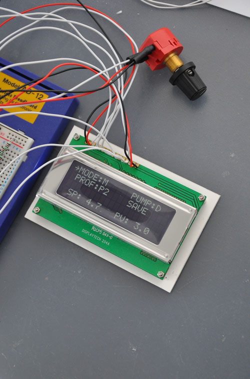
One pot controls the SP value and the other one changes the PV. With both analogue channels active when I change the SP the PV changes as well and vice-versa. It's not random numbers, when I turn the pot 'up' the values increase etc. Also when I set the SP pot to max the PV pot works as it should, if I set the SP pot to 0 the PV pot shows only part of the full range of numbers it should (should go from 0.0-9.9, but goes from 0.0 to 2.6 only).
I tried putting a delay (5ms and even 500ms) between the SP pot read and the PV pot read, but it changes nothing. When using a 500ms delay between the two reads I've noticed that first the correct value changes and then it also affects the second value which normally should not happen (as it's controlled by the second pot). It looks like there's something left in the ADC registers, as if the conversion hasn't finished yet, but that can't be as I'm checking the DONE bit before processing the values.
Perhaps someone here had a similar problem or sees something obvious that I've missed? Would appreciate any help. Thanks!
Regards,
dsc.
EDIT:
I've simplified the ADC_loop function a bit:
first of all, Nigel's website seems to be down:
so I thought I would ask on the forums.
I'm using a PIC16f877A and I've configured it to read two ADC inputs on pins 0 and 1 of PORTA, there's also a Vref+ on pin 3. It all works well when I'm reading from one source at a time, but when I try to read from both of them, one after the other it goes sideways and I'm getting strange values on the LCD (which is hooked up to the PIC). The two analogue inputs are pots, one 10k and one 0.5k as they were the only ones I had at hand.
Here's the code for the first pot ADC:
Code:
Read_pot

		;############# read the pot ##################

		; setup the input for the pot

		bcf		ADCON0, 3		;select AN0
		bsf		ADCON0, 2		;ADC ON
		call		ADC_loop
		movf		low_b, W		;copy low_b to W
		movwf		pot_value		;move W(low_b) and save in pot_value

		retlw		0x00
and here's the code for the other pot (which will be a pressure transducer in the final system):
Code:
Read_PT

		;############# read the PT ##################

		; setup the input for the PT
		bsf		ADCON0, 3		;select AN1
		bsf		ADCON0, 2		;ADC ON
		call		ADC_loop
		movf		low_b, W		;copy low_b to W
		movwf		PT_value		;move W(low_b) and save in PT_value

		retlw	0x00
The function ADC_loop used for both looks like this:
Code:
ADC_loop

		btfsc		ADCON0, 2		;test DONE bit
		goto		ADC_loop		;loop until it's done

		movf		ADRESH, W		;move ADRESH to WREG
		movwf		high_b			;move W to HIGH
		; ADRESL is in Bank 1!
		bsf 		STATUS,	RP0		;select bank 1
		movf		ADRESL, W		;move ADRESL to WREG
		bcf 		STATUS,	RP0		;select bank 0 again
		movwf		low_b			;move W to LOW

		RRF 		high_b, F		;remove the last 3 LSBs
		RRF 		low_b, F		;which means dividing the 1024
		RRF 		high_b, F		;value by 8, giving a 127 bits value
		RRF 		low_b, F		;in low_b
		RRF 		high_b, F		;
		RRF 		low_b, F		;

		retlw	0x00
Now, what's happening with both pots active is that when moving one pot the values shown for the other one are changing as well. The display looks like this:
One pot controls the SP value and the other one changes the PV. With both analogue channels active when I change the SP the PV changes as well and vice-versa. It's not random numbers, when I turn the pot 'up' the values increase etc. Also when I set the SP pot to max the PV pot works as it should, if I set the SP pot to 0 the PV pot shows only part of the full range of numbers it should (should go from 0.0-9.9, but goes from 0.0 to 2.6 only).
I tried putting a delay (5ms and even 500ms) between the SP pot read and the PV pot read, but it changes nothing. When using a 500ms delay between the two reads I've noticed that first the correct value changes and then it also affects the second value which normally should not happen (as it's controlled by the second pot). It looks like there's something left in the ADC registers, as if the conversion hasn't finished yet, but that can't be as I'm checking the DONE bit before processing the values.
Perhaps someone here had a similar problem or sees something obvious that I've missed? Would appreciate any help. Thanks!
Regards,
dsc.
EDIT:
I've simplified the ADC_loop function a bit:
Code:
ADC_loop

		btfsc	ADCON0, 2		;test DONE bit
		goto	ADC_loop		;loop until it's done

								;as it's left justified the 8bit value is in ADRESH
		movf	ADRESH, W		;move ADRESH to WREG
		movwf	high_b			;move W to HIGH


								;now the 8bit value is in high_b so
		RRF 	high_b, F		;to get 0-127 we RRF once and save in low_b
		movf	high_b, W		;copy to W
		movwf	low_b			;copy from W to low_b


		retlw	0x00
Last edited:
