Continue to Site

Welcome to our site!

Electro Tech is an online community (with over 170,000 members) who enjoy talking about and building electronic circuits, projects and gadgets. To participate you need to register. Registration is free. Click here to register now.

  • Welcome to our site! Electro Tech is an online community (with over 170,000 members) who enjoy talking about and building electronic circuits, projects and gadgets. To participate you need to register. Registration is free. Click here to register now.

Trying to make this counter work!

Status
Not open for further replies.

Iawia

Member
Hi,

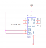
I am trying to use a counter in my design (NTE74HC161N). Can someone tell me how to use it?

I have a clock that is pulsing that i want to be the input to this counter. but there are so many inputs.

i have grounded all inputs ABCD to give me a start at zero, put 6 V on pin 16, GND for pin 8.
6 V for Enable P and T, and still i can't get it to count when I load zeros into the input, i get no change on the output when i clock the output once.

is there something i am doing wrong? p.s. i have loaded the .pdf of the counter that i am using.
 

Attachments

  • Synchronous Counter NTE74HC161N.pdf
    67.7 KB · Views: 128
Need to post a schematic.

What are you doing with the Load and Clear input? You can't leave any inputs floating.
 
Hi crutschow,

I am getting some outputs now after your suggestion. but it is not counting in binary sequence. it'll go from 0000 to 0001 to 1000 to 0000. i don't understand the sequence.
I have put 'master reset' and 'load' to high according to the .pdf from philips of the chip with the same number (attached).

Can you offer anymore suggestions?
 

Attachments

  • Synchronous Counter NTE74HC161N_Phillips.pdf
    79 KB · Views: 125
Last edited:
The attached image should be how your counter is configured. That is all that is needed. Pin 1 is tied high to count, placing it at a low will reset the count. Make sure there is no noise or switch bounce on the clock input.

Ron
 

Attachments

  • 74161 Counter.png
    74161 Counter.png
    8.1 KB · Views: 163
What do you mean by switch bounce on the cp?

I have a breadboard with the chip set up, and I am trying to simulate the clock by placing a wire to ground then to Vcc, and to simulate the second pulse would go from ground to Vcc again. Is this wrong?
 
What do you mean by switch bounce on the cp?

I have a breadboard with the chip set up, and I am trying to simulate the clock by placing a wire to ground then to Vcc, and to simulate the second pulse would go from ground to Vcc again. Is this wrong?

Yes, that is not a good way to simulate a clock pulse. The clock in needs to be nice clean pulses. If you could see what you are doing on a scope your simulated clock pulses would be a mess of jitter and noise as you can't get a nice clean make and break. Even a push button switch would give you noise and an erratic count. Thus the term "switch bounce". Give this link a look. Or just do a Google of Switch Bounce to see exactly what I am getting at.

Something you can try is place a 10 K Ohm resistor between your clock in pin and Vcc ( a pullup) and place a .1 or .01 uF cap to ground from your clock in pin. Now tap the clock in to ground to clock the chip. Since the counter increments up on a low to high each time you break ground to the clock in the counter should count up. If your circuit is what I posted and is erratic as you describe the problem is switch bounce.

Ron
 
Hey thanks Ron. I think it is counting properly now. I hooked it up to a tlc555 timer. I wont know for sure until i implement the decoder. Thanks. I really appreciate your help.
 
Your link to switch bounce was also very helpful. No wonder my outputs were not sequential. It made several bounces each time.
 
Good and glad it seems to be working out. Our pleasure to help.

Ron
 
Status
Not open for further replies.

Latest threads

Back
Top