Continue to Site

Welcome to our site!

Electro Tech is an online community (with over 170,000 members) who enjoy talking about and building electronic circuits, projects and gadgets. To participate you need to register. Registration is free. Click here to register now.

  • Welcome to our site! Electro Tech is an online community (with over 170,000 members) who enjoy talking about and building electronic circuits, projects and gadgets. To participate you need to register. Registration is free. Click here to register now.

true power vs apparent power

Status
Not open for further replies.

HATHA

New Member
hi all
i have a question about true power, and apparent power. lets say some reactive load, i mean inductive and capacitive load drive with ac main. is
true power = Irms x impedence across the load (at f=50Hz)?
apparent power = Irms x Vrsm across the load ?

my intention find the powe factor, and i don't have watt meter.

thank you
 
"true power = Irms x impedence across the load (at f=50Hz)?"

This is incorrect. A possible way to express true power would be:

true power = Irms^2 x real part of the load impedance (at f=50Hz)

But then you have the problem of measuring the real part of the load impedance.

If you don't have a wattmeter, you might be able to use an oscilloscope to measure power if you have a scope with a math function that can calculate the product of channel 1 (displaying instantaneous load current) and channel 2 (displaying instantaneous voltage across the load), then average that product. This is the equivalent of a wattmeter.

There is a low-cost wattmeter that is widely available which can measure up to a kilowatt or so, and display power factor:

P3 - Kill A Watt

Kill A Watt - Wikipedia, the free encyclopedia
 
Last edited:
"true power = Irms x impedence across the load (at f=50Hz)?"

This is incorrect. A possible way to express true power would be:

true power = Irms^2 x real part of the load impedance (at f=50Hz)

[/url]
i'm sorry my bad typing mistake(Irms insted of Irms^2). if channel 1 represent Irms and channel 2 represent Vrms then you mean that true power is the product of Irms and Vrms so what is mean by apparent power.
 
Last edited:
Channel 1 of the scope won't be displaying RMS current, but rather instantaneous current, and channel 2 will be displaying instantaneous voltage across the load, not RMS voltage. The math function will display the instantaneous product of the two, and this will be the instantaneous power. Averaging this will give the true power.
 
ok, i know scope does not show the rms value(instead wave form) my intention is to determine power factor. so how can i find the apparent power?
furthermore, attachment is what i get from scope. yellow wave is voltage across load and the blue wave show the current through 1.193Ω resistor series with load
 

Attachments

  • measurement.png
    measurement.png
    43.9 KB · Views: 357
ok, i know scope does not show the rms value(instead wave form) my intention is to determine power factor. so how can i find the apparent power?
furthermore, attachment is what i get from scope. yellow wave is voltage across load and the blue wave show the current through 1.193Ω resistor series with load

You can determine the apparent power by measuring the RMS value of the current and voltage with an ordinary DVM (or with a scope as I do below).

I think I recognize the current waveform in your scope capture; it looks like a compact fluorescent lamp is being measured.

I connected a CFL in series with a 1.000 Ω resistor and captured the current and voltage waveforms.

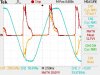
In the attached image, the orange waveform is the current, the blue waveform is the voltage and the red waveform is the math waveform (the instantaneous product of the current and voltage). The true power will be the mean of the instantaneous product of the current and voltage.

You can see on the right side of the image the RMS value of the current (.177 amps RMS), the voltage (123 volts RMS) and the true power (12.7 watts). The product of the RMS current and the RMS voltage is the apparent power, .177 * 123 = 21.771 VA. The power factor is 12.7/21.771 = .58

You could measure the RMS current and voltage with a digital voltmeter (one that can measure true RMS) instead of the scope.

If your scope can't make these measurements, perhaps you can capture the current and voltage waveforms as .csv files and do the math on them with Matlab or some similar program.

You could connect additional resistor(s) in parallel with your 1.193 Ω resistor to make the combination more nearly 1.000 Ω; 6.18 Ω would do the job.
 

Attachments

  • ScopePower.jpg
    ScopePower.jpg
    39.9 KB · Views: 328
thank you The Electrician, thank you again for spending your time for my problem. things are more clear than ever. sadly the scope i use do not have mult math function, but was able to get wave form data to .csv file. using ms excel i think i can do required calculation. further, the load is not CFL. it is 7W HB led bulb.

HATHA
 
Status
Not open for further replies.

New Articles From Microcontroller Tips

Back
Top