Continue to Site

Welcome to our site!

Electro Tech is an online community (with over 170,000 members) who enjoy talking about and building electronic circuits, projects and gadgets. To participate you need to register. Registration is free. Click here to register now.

  • Welcome to our site! Electro Tech is an online community (with over 170,000 members) who enjoy talking about and building electronic circuits, projects and gadgets. To participate you need to register. Registration is free. Click here to register now.

Troubleshooting Parallel Serial Programmer

Status
Not open for further replies.

madchemist2227

New Member
Ok, I have had a rough time (as everyone else it seems) trying to program PIC16F84a 20MHz microcontroller. I have tried many types of serial designs with all kinds of software (except the dos ones) with no luck. However that was using voltage from the port itself and not an external powersupply wich may work.

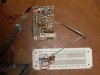
So I decided to try the parallel port. I built an in-circuit parallel programmer based on the "par-pic" design (if you dont know use google). The only difference is I modified the artwork and added a power supply using a 7805 and 7812 regulator for the 5V and 13V from 18V of batt power. Below is a photo of the finished programmer.

<a href="http://smg.photobucket.com/albums/v205/madchemist/?action=view&current=parpic2.jpg" target="_blank"><img src="http://img.photobucket.com/albums/v205/madchemist/parpic2.jpg" border="0" alt="Parpic"></a>

I can't get this programmer to work with any of the traditional software. I have heard windows xp has issues with the lpt port, should I try it in dos? It'll of course read but it wont program. Most software wont even recognize that there is a programmer there. Is it a hardware problem or software?

Also, the original schematic used BC547 transistors, I used BC548, could that cause a problem?
 

Attachments

  • parpic2.JPG
    parpic2.JPG
    1.6 MB · Views: 208
Last edited:
XP works fine with PIC programmers via the parallel port, one cause of concern is the long length of wire from programmer to chip, and the fact you have the chip in a breadboard. These both add extra capacitance, and most parallel port programmers (and serial ones) require very low capacitance to work - this is because they normally use resistor pullups, and the capacitance slows the rise time.

I would strongly suggest you buy either a PICKit2, or Bill's Junebug clone, the days of parallel and serial port programmers are over now.
 
I'd still like to have a parallel port on a PC, it's just such a handy thing to have for general electronics work. It's harder and harder to find them though.
 
Well, the programmer listed here (**broken link removed**) uses the same type of interface on a breadboard and they make no mention of any problems due to capacitance. If it is indeed that, what are some ways to combat it? Could the length of cable from port to programmer? Its sheilded and grounded and everything.

I dont wanna buy a programmer not when I can build one for a fraction of the price.
Besides, how can I build anything that works using the PIC's if I can't even build a working programmer dammnit!

This is the url for PAR-PIC-
(Google Image Result for http://www.ubasics.com/adam/pic/archive/parpic.gif)

I just noticed at the bottom it offers software to use with it based on PP-V-0.5 program. I should probably try the suggested software before claiming it doesnt work just yet.
 
Oh ok I see what you mean, the dirty connections of the breedboard causes capacitance that affects rise/fall time with the resistors on the board. Well, I dont have any type of circuit built for the PIC yet so I cannot hardwire it. I can maybe solder a socket to a peice of protoboard, and then solder the programming header to the protoboard and place the PIC in the socket.

Most PIC programmers use sockets, wouldnt that cause some type of added capacitance or is the connection sturdy enough?
 
Well I tried using the recommended software and I still couldnt get it to work. It said to make and use a dos batch file but when I did that and ran it it did not ask to apply voltage like the insturctions said it just basically did nothing.

Maybe I shouldnt have added the power supply to this. I might cut those traces and wire up a resistor and zener like in the original schematic. Also, I noticed the original par-pic does not supply +5V to the Vdd, just the 13V MCLR. Do you need both Vdd and MCLR when programming? Or do you just need the 13V MCLR?

Also, in my board the 12V regulator seems to get quite warm. One time I tested it it got so hot it burned the **** out of my finger and some laquer that got sprayed on it began to smoke. I quickly disconnected it.
 
Although the parallel port programmers fair better than the JDM style serial port programmers they can still be more trouble than their worth.

The PIC MCLR needs about 11V to put a PIC into program mode, GND will reset it and 5V will allow it to run.

PS the ParPIC design is from 1998 and no longer supported by Mr. David Tait. Besides a few 16F84As will cost you more than a proper MPLAB compatible programmer.
 
Last edited:
Well I tried using the recommended software and I still couldnt get it to work. It said to make and use a dos batch file but when I did that and ran it it did not ask to apply voltage like the insturctions said it just basically did nothing.

Maybe I shouldnt have added the power supply to this. I might cut those traces and wire up a resistor and zener like in the original schematic. Also, I noticed the original par-pic does not supply +5V to the Vdd, just the 13V MCLR. Do you need both Vdd and MCLR when programming? Or do you just need the 13V MCLR?

Look again, you need both, and par-pic supplies both.

Also, in my board the 12V regulator seems to get quite warm. One time I tested it it got so hot it burned the **** out of my finger and some laquer that got sprayed on it began to smoke. I quickly disconnected it.

If the regulator is getting hot like that you've done something seriously wrong, it should run cool.
 
It never ran hot like that before only that one time.

Oh yeah as far as a few PIC's being more expensive than a programmer, I think not. The cheapest programmer I have seen is like $40-$50 and a few PIC's is around $12.
I might just breakdown in the future and buy a programmer but I just got fired from my job so spending money on a hobby is not an option right now. Besides I already have all the parts to build pretty much any programmer in the book laying around so I might as well try and make something work damn it.
 
ICSP programmers are under 20 dollars.
 
Last edited:
For a start connect it up properly, if you don't connect 5V it can't possibly work.

Well no kidding? I had the 5V connected from the start I'm not that stupid. I was just asking if it was needed since the original parpic only supplied the 13V, but I see that the circuit was meant to supply the 5V. I just modified the parpic with a 7805 to supply it without it being "in-circuit".

Anyways maybe I should just quit being lazy and finish my tait programmer. That ones half built on a proto board and all that soldering gets old after a while. How well do tait's work?
 
Last edited:
Well no kidding? I had the 5V connected from the start I'm not that stupid. I was just asking if it was needed since the original parpic only supplied the 13V, but I see that the circuit was meant to supply the 5V. I just modified the parpic with a 7805 to supply it without it being "in-circuit".

Anyways maybe I should just quit being lazy and finish my tait programmer. That ones half built on a proto board and all that soldering gets old after a while. How well do tait's work?

There are many different Tait programmers, he's quite rightly the 'father of PIC programmers' - most later designs are based on his, for example, the excellent P16PRO40 is based on his standard design. However, what you should avoid is his first 'effort' that used a CMOS switch, this was a poor idea, and stems from the fact David wasn't a 'hardware guy'.
 
Status
Not open for further replies.

Latest threads

New Articles From Microcontroller Tips

Back
Top