Continue to Site

Welcome to our site!

Electro Tech is an online community (with over 170,000 members) who enjoy talking about and building electronic circuits, projects and gadgets. To participate you need to register. Registration is free. Click here to register now.

  • Welcome to our site! Electro Tech is an online community (with over 170,000 members) who enjoy talking about and building electronic circuits, projects and gadgets. To participate you need to register. Registration is free. Click here to register now.

Trouble with Shocker

Status
Not open for further replies.

Cry_Wolf

New Member
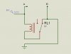
I decided to build a shocker that operates at 6V. I build the following circuit. It worked fine and when i powered it it gave me humming sound which means that the relay was switching on and off at very high frequency.

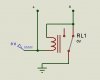
But the problem is when i connected a small mini transformer(Which i got from a my cheap old charger) across point A and B it did'nt worked.

What could be the problem. I know the problem is with the transformer, Can any one tell me which transformer to use??
 

Attachments

  • shocker.JPG
    shocker.JPG
    10.7 KB · Views: 155
Well if you say that polarities are wrong in my diagram, then again my circuit is not working because i tried by both the ways
 
Shocker

Did you verify that the transformer you used is only a transformer and does not contain any rectifiers? You don't want a rectifier to shunt your generated high voltage, so it must be a true transformer with the low voltage secondary connected across the coil of the relay to give you the required step-up. (Important also is that the impedance of the transformer winding should be approximately equal to the impedance of the relay coil, otherwise the current will have a preference for which ever one has the lower impedance). (Output is on the high voltage side).

Try to find an open type relay and wind a few thousand turns of very thin wire on top of the existing coil if space allows it. This winding can then be used as the high voltage output. (Just a thought!).
 
Last edited:
Cry_Wolf said:
Well if you say that polarities are wrong in my diagram, then again my circuit is not working because i tried by both the ways

I didn't say the polarity was wrong, I said you've connected the transformer to completely the wrong place - and it's nothing like the link you posted.

I'll give you an extra clue (although there's almost no components to get confused by) - you've connected your transformer directly across the battery!.
 
Ok I got it, actually i drew the schematic wrong in hurry. So here's the schematic of the circuit which actually i made.
 

Attachments

  • shocker.JPG
    shocker.JPG
    14.4 KB · Views: 159
That should work then, although personally I'd probably connect point B to the other relay contact, so it 'makes' as the relay switches.

There's really nothing to go wrong, unless you wire it wrong.
 
Ok can you tell me which transformer to use. I actually broke a old nokia charger to get a transformer if you can specify one it would be helpful. :D
 
Nigel Goodwin said:
There's really nothing to go wrong, unless you wire it wrong.
The relay will expire pretty quickly as they're not designed to work at that frequency.
 
any alternative to relay??

Actually i am having a party soon in my university :D so i am in urgent of a shocker ;). Any help would be appreciated.
 
Hero999 said:
The relay will expire pretty quickly as they're not designed to work at that frequency.

It's not like you're wanting it to run for days at a time, it should certainly last much longer than it takes to get bored with it - and has the added advantage that it will stop working well before the hospital get around to removing it from where it gets shoved! :p
 
Yup. "Beer is proof that God loves us and wants us to be happy"
B. Franklin
 
a disposable camera, solder leads to the caps. Simple.
 
Status
Not open for further replies.

Latest threads

New Articles From Microcontroller Tips

Back
Top