Electro Tech is an online community (with over 170,000 members) who enjoy talking about and building electronic circuits, projects and gadgets. To participate you need to register. Registration is free. Click here to register now.
Welcome to our site! Electro Tech is an online community (with over 170,000 members) who enjoy talking about and building electronic circuits, projects and gadgets. To participate you need to register. Registration is free. Click here to register now.
From first glance, it would appear that you need to add a ground reference to some point of the circuit (press 'G' to place the ground). Also make sure that you've assigned every part a value (right-click on the parts); e.g. you need to set what type of diodes are to be simulated, the value of the capacitors & voltage/current sources too.
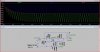
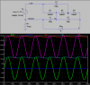
Thanks you for your replied.I had been modified the circuitry according to your suggestion but I can not get the expect result.Below is updated schematic and after simulated waveform for your reference,also I had indicate the test point at circuitry V(n002~V(n004).
The output must be taken differentially across the "load". The diodes must have a PIV of ~1000V. I rearranged it to create a positive output voltage relative to Neutral (which is at ground potential).
Thanks you Mike,
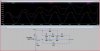
I had been modified the schematic as same as you shown at that topic.After done the simulation at LTspice I can not get the expect simulate result,the doubler and tripler output point start very slow and very large ripper.I guess the problem come from those capacitors (it is my first time use LTspice to do the simulation so I use the library components) wich I got from LTspice library,I don't know how to create a new one or modify the existing part.
I had attached schmatic file (Tripler circuit_1) would you mind do the correction at my circuitry for me such that I can continue my simulation,also the simulated waveform given at the attachment.
Moreover this is my first time using tripler circuit would you please explain what is the function of 1MEG resistor at your schematic ?
Your LTSpice simulation is doing exactly what you are telling it to do. By saying .TRAN 100ms, you are simulating the time history of the circuit for only about the first 6 cycles of the 60 Hz input. Since at t=0, the voltage source =0V, all of the capacitors start out with 0V across them. It takes many cycles since start-up for the circuit to reach steady state, where the capacitors have charged to their "operating" state.
To get to the steady state, you will need to lengthen the time to run the simulation by changing to .TRAN 1. Now you will see what happens over the first 60 cycles. If you don't care to see the start up, and want to see only the ripple component after the circuit reaches steady-state, then use .TRAN 1 0.83, which runs the simulation for 1s, but doesn't start plotting data until 0.83s into the run, meaning it will plot only the last few cycles...
Note that a real voltage tripler operating at 60Hz input would have a long start-up time, and lots of ripple, too. The startup time is a function of the size of the capacitors, as well as the current I1 being drawn off the output. Note that to see the ripple across the "load", you would normally plot V(n005)-V(n004). However, since there is no current flow through R1, the voltage at V(n005) is zero.
The reason I put R1 in the circuit is because all Spice variants require one node in the circuit to be defined as "ground" (GND: node 0 in the netlist). What you call "ground" is arbitrary, and I could have made n005 GND by attaching the ground symbol to it directly. The other way to do it is to add an arbitrary high-value resistor (the other end of which is GND) to one of the "floating" circuit's nodes. The current flow in this mythical resistor is zero anyway, so it has no real effect on the circuit, but it satisfies the requirement that "at least one node be GND".
In the US, one side of the 60Hz 120V AC line is at "earth ground" potential, and that is the white wire, called Neutral. Any voltage tripler powered by the 60Hz 120V AC line would likely configure the tripler so that its output is taken the way I drew it, i. e. the tripled voltage is taken with respect to Neutral, not the other line (Black or L).
Much thanks MikeMI,
After set the stop time to 1 and start plot data time to .9 I got the same similution result as same as your.One more question is that if I actually build the tripler circuitry the 1meg resistor should not use,am I right ?
This site uses cookies to help personalise content, tailor your experience and to keep you logged in if you register.
By continuing to use this site, you are consenting to our use of cookies.