Good Afternoon
I am busy building a static VAR compensator for a project and i need to use TRIACS to switch in my capacitor banks. The system is 3 phase 400 VAC and consists of 3 motors with varying loads. There is a system that determines the power factor and switches in the capacitors. Today all my TRIACS blew when I put a 1.1kw motor on. I am using Q6030LH5 TRIACS and MOC3021 optocouplers.
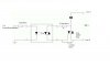
The thing is, the switching circuit was not connected to the microcontroller yet. Therefore the switches should be completely off. The capacitors are connected as shown on the attachment.
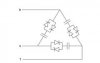
The optocoupler and TRIACS are connected as shown in the other attachment. The resistor used between the optocoupler and triac is not 220 ohms but 100 ohms and the other resitor i not 330 ohms but 2 kilohms.
I hope this makes sense and this is urgent.
Kind Regards
DillenM
I am busy building a static VAR compensator for a project and i need to use TRIACS to switch in my capacitor banks. The system is 3 phase 400 VAC and consists of 3 motors with varying loads. There is a system that determines the power factor and switches in the capacitors. Today all my TRIACS blew when I put a 1.1kw motor on. I am using Q6030LH5 TRIACS and MOC3021 optocouplers.
The thing is, the switching circuit was not connected to the microcontroller yet. Therefore the switches should be completely off. The capacitors are connected as shown on the attachment.
The optocoupler and TRIACS are connected as shown in the other attachment. The resistor used between the optocoupler and triac is not 220 ohms but 100 ohms and the other resitor i not 330 ohms but 2 kilohms.
I hope this makes sense and this is urgent.
Kind Regards
DillenM
")