Continue to Site

Welcome to our site!

Electro Tech is an online community (with over 170,000 members) who enjoy talking about and building electronic circuits, projects and gadgets. To participate you need to register. Registration is free. Click here to register now.

  • Welcome to our site! Electro Tech is an online community (with over 170,000 members) who enjoy talking about and building electronic circuits, projects and gadgets. To participate you need to register. Registration is free. Click here to register now.

Treadmill board component burn repair

Status
Not open for further replies.

Tansmile

New Member
Hi
I hav treadmill board burned. There are 2 component burn out and i am looking for replace it.However, i am not sure what is the value of the components, can anyone expert advise here? Thanks in advance.
20220304_085304.jpg

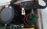
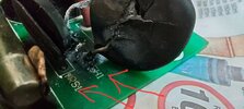
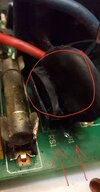
The 2 components labeled as RS1 and TH1 burned look like seramic caps. They are connected to rectifier KBPC3510N.


20220227_162244.jpg

The treadmill board is KPT451Driver ver2.1 2008/12/13.

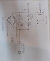
I need helps to identify the component RS1 and TH1 and thier values.

20220304_085321.jpg
 
Last edited:
Cause has to be established. The large cap is bulging at top which suggests
it needs to be replace. That could have caused a short and taken out bridge,
square package with 4 lugs on it. I would also check power fets bolted to heat-
sink.

The disk shaped part probably a varistor or MOV, try to read the part labeling
on its side. Its a transient V protector for circuits.

Try to get a schematic for it and post that so forum can give you additional guidance
on what to check. Or hand draw one.

Regards, Dana.
 
Might be just the picture angle but that cap looks fine to me.

There is an earlier version of that pcb on Aliexpress but no clear shot of the values of the components.

I suspect the bridge rectifier is shorted which has taken out the MOV, possibly a cap and the fuse.
 
The large cap look like either of these ?

1646395817428.png


1646395841116.png


Also any of the smaller caps look like this -

1646395992477.png


The above all suspicious.


Regards, Dana.
 
Thank you for responce.
Yes, these burn mark having these 2 components burned. I think they are Ceramic caps, but i dont know the value.

If anyone experts in Rectifier design and can give a guess on these 2 components value. I tested the bulk caps is fine and the rectifiers also good..
 

Attachments

  • 20220304_085321.jpg
    20220304_085321.jpg
    1.1 MB · Views: 210
  • 20220227_162244.jpg
    20220227_162244.jpg
    661.9 KB · Views: 217
  • 20220226_210151.jpg
    20220226_210151.jpg
    527.4 KB · Views: 222
Thank you for responce.
Yes, these burn mark having these 2 components burned. I think they are Ceramic caps, but i dont know the value.

If anyone experts in Rectifier design and can give a guess on these 2 components value. I tested the bulk caps is fine and the rectifiers also good..

I think those are MOVs, not ceramic caps......

How are you testing the caps ?
 
Last edited:
Try my best to draw part of the schematic from the circuit board.
 

Attachments

  • 20220306_213019.jpg
    20220306_213019.jpg
    738.3 KB · Views: 216
I suspect either TH1 or RS1 is in series with the input to the bridge rectifier, as an inrush current limiter?
 
Hi everyone, I have the same problem the 2 ceramic capacitors have exploded, you can read something but I'm not an expert, if someone can help.
P_20220524_175138.jpg

P_20220525_181246.jpg

P_20220525_181318.jpg


as soon as I can I try to unsolder it and post a better photo.
 
Status
Not open for further replies.

Latest threads

New Articles From Microcontroller Tips

Back
Top