Continue to Site

Welcome to our site!

Electro Tech is an online community (with over 170,000 members) who enjoy talking about and building electronic circuits, projects and gadgets. To participate you need to register. Registration is free. Click here to register now.

  • Welcome to our site! Electro Tech is an online community (with over 170,000 members) who enjoy talking about and building electronic circuits, projects and gadgets. To participate you need to register. Registration is free. Click here to register now.

Trash to Treasure project

Status
Not open for further replies.

MrDEB

Well-Known Member
This is a last minute gift for my wife. Had no idea she wanted flame less candles.
Well I have three different sized tin cans (trash), laminated white paper to resemble candles.
Working on the pic controlled flicker that has a CDS cell for turning on the candles upon dark.
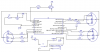
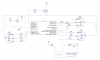
Have extra Nimh battery pack that when charged shows 5.45 volts, thus the diode on the Vdd .
resistor R10 needs to be determined as I want to enable all 9 leds under pic control but 470 should be in the ball park.
The PNP transistor is a TIP 32. Yes it is on the large size but its all I could locate.
the pot is for adjusting for light condition after completion. May need to add additional resistance??
Need to research weather to put the pic to SLEEP or IDLE during daylight?
 

Attachments

  • candles pic.zip
    69.8 KB · Views: 208
Such an enormous file and impossible to read. Could you try something more reasonable?
 
The file was huge (15.1MB) because it was as big as my neighbourhood and was saved as a BMP file type.
I copied it and reduced its size to half, cropped it a little then saved it as a 53.1KB PNG file type:
 

Attachments

  • candles pic.png
    candles pic.png
    53.2 KB · Views: 239
Creating a readable schematic has been explained to MrDEB dozens of times. Friendly advice....don't waste any effort trying again.
 
Its been awhile. At least I compressed it and made it with a white background. My bad I should have gone with the jpeg
 
here it is in png format at 300dpi
The dip trace will only do jpeg or bitmap so I used infaview to put it as a png.
Have the main circuit working but trying to get a simple transistor to work.
The actual current draw is 40ma so a 4.7K resistor on the base should be right but I was not going in right direction using the PNP but after looking at my schematic it should work. I have a hunch it is something really simple and I have overlooked.
taking a break as I have been sorting out a short on one of the cathodes. A small dab of solder is too simple but easily overlooked.
 

Attachments

  • candle schematicjpeg.png
    candle schematicjpeg.png
    334.9 KB · Views: 214
By the way...not to hijack MrDEB's thread....

There are terminal emulators for Android devices that support the CH340G USB chip in the schematic above. If you have a phone that supports USB To Go, you can interact with a dev board using the above chip right from your phone. That's just kind of awesome.
 
Don't have an Android. Only a dumbass flip phone. Have really no need for one of them smartass phones.
After taking a lunch break and contemplating what I have and why it dosen't want to turn on the transistor (PNP) I reconfigured and it now turns on . Need to look at my calculations for the base resistor. Don't think they are right but in the ballpark
 
The comment about the UART circuit and phone wasn't really meant for MrDEB. I only made it to explain the example schematic I posted in case anyone is interested.
 
With electronics, there are usually many different ways of accomplishing a task, with no best or right approach. Whatever method helps a person accomplish the task is the best approach for him.

In MrDEB'S case, Diptrace will output either a bmp or jpg image, not a png. If he exports the image with enough resolution, a jpg will be great. Telling him he must post a png complicates the process and since changes are he converted a jpg to a png, it doesn't result in a better image.

I have noticed a certain...rigidity....in responses posted here recently, particularly by people with fancy membership titles. They tell people there's only one way to do things or the way they are trying to do it is a waste of time. Sure, offer suggestions and alternative methods but don't imply a person is stupid or wasting their time because it's not the way you would do it.
 
  • Like
Reactions: jjw
In MrDEB'S case, Diptrace will output either a bmp or jpg image, not a png. If he exports the image with enough resolution, a jpg will be great. Telling him he must post a png complicates the process and since changes are he converted a jpg to a png, it doesn't result in a better image.

And how are we supposed to know he's using an antiquated program to generate his pictures?, Windows Paint happily saves PNG's and it's trivial to load a BMP and resave it as a PNG.

Simple courtesy when posting on forums.

We've all seen massive BMP posted here, and totally illegible JPEG's as well - it's as easy to convert from BMP to PNG as to save JPEG's with minimal compression.
 
And how are we supposed to know he's using an antiquated program to generate his pictures?, Windows Paint happily saves PNG's and it's trivial to load a BMP and resave it as a PNG....

....We've all seen massive BMP posted here, and totally illegible JPEG's as well - it's as easy to convert from BMP to PNG as to save JPEG's with minimal compression.

I assume you could know the same way I know....by reading what he posted.

Yes, it should be an easy matter to convert a bmp to a png, but having seen MrDEB convert a 200 pixel wide jpg into a 5000 pixel wide png in the past and not have a clue why it was still unreadable, often it's not that simple.

I'm not advocating people posting huge bitmaps. What I am saying is a jpg WILL provide simular results to a png at a similar file size, so you shouldn't let it offend your delicate sensibilites.
 
jpeg, bmp, png, it is an interesting subject at best.
I have moved on to calculating the base resistor and as usual when math is involved I get lost. Several years ago someone suggested just multiply the collector / emitter by a factor of 10. Now I get lost.
5v at the collector (pnp tip32) and the Leds use 40ma actual current (while enabled) which equates to 125 ohms
125 x 10 = 1250 ohm resistor.
Is this a right assumption??
 
Well I think I found the solution??
(5v Vcc - .7Vb) / (40ma / 10) = 1075 ohm resistor
time to change my base resistor.
transistor base---1K resistor---junction to pic port---10k pull-up ---5V
l
l
 
As shown in its datasheet, the TIP32 transistor turns on pretty well when its base current is 1/10th its collector current so with 40mA of collector current its base current must be 4mA.
Its datasheet also shows that with 40mA collector current and 4mA base current then its typical base-emitter voltage is 0.65V and assuming that the voltage loss of the PIC output at 4mA is 0.2V then the base resistor voltage will be (5V - 0.65V - 0.2V)/4mA= 1038 ohms so the 1k is perfect.
 
Thanks Audioguru.
After progressing with the transistor section I am contemplating putting the pic to SLEEP during daylight but Swordfish has no SLEEP command in its library that I could find. Thinking just using a 8 hour timer (5pm to 12 midnight) then the transistor (leds) are disabled to conserve power. Using a 1600mah Nimh battery pack and 50ma current draw the battery will run say 22 hours aprox. Have to recharge every three days!! need to rethink this. On / Off switch looks like solution??
 
Status
Not open for further replies.

Latest threads

New Articles From Microcontroller Tips

Back
Top