Continue to Site

Welcome to our site!

Electro Tech is an online community (with over 170,000 members) who enjoy talking about and building electronic circuits, projects and gadgets. To participate you need to register. Registration is free. Click here to register now.

  • Welcome to our site! Electro Tech is an online community (with over 170,000 members) who enjoy talking about and building electronic circuits, projects and gadgets. To participate you need to register. Registration is free. Click here to register now.

Transistor

Status
Not open for further replies.
hi,
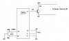
For the purpose of deciding the transistor, assume you have the ideal transistor.

Now show us on you circuit diagram where you intend connecting this ideal transistor.
Not a block diagram that you posted earlier, but a circuit diagram.:)

When we can see how the ideal transistor is connected and what it does, we can advise an actual transistor type number.
 
Here is the diagram

I think i understand more about transistor thanks to hero999

I just want to find a database for transistor or place to search for it because google is not helping and i don't have exact value to search for therefore if you know a website that have a database for transistor i appericate it
 

Attachments

  • PIC&transistor.JPG
    PIC&transistor.JPG
    14.3 KB · Views: 127
Last edited:
What does R2 represent?

Any chance you know how much current it draws?

Just look through catalogues of component suppliers and find a transistor with a suitable hFE, Vce and Ic.
 
it uses ic = 1.049A
R2 is just a resistor don't know why i must use it i saw NPN transistor always uses R1 and R2.
 
Well you must know what R2 is as you know the collector current.

Assuming the MCU has a maximum output of 25mA you need a transistor with a gain of at least 40 at 1A (good luck) and the minimum IC needs ot be at least 1.2A.

My advice is to use a logic level MOSFET.
 
For the load current of 1.05A you need a darlington transistor that will switch it when its base current is only 25mA or less. A TIP110 darlington transistor has a typical saturation voltage loss of 0.9V when its collector current is 1.05A and its base current is 10mA. Its max voltage loss might be 2V.
 
uaefame said:
it uses ic = 1.049A
R2 is just a resistor don't know why i must use it i saw NPN transistor always uses R1 and R2.

hi uaefame,

The motor in the Energy convertor, does it have to drive in a clockwise and anticlockwise direction when its working.?

Also does the motor have to move/drive at different speeds.?

How many wires on the motor are free for you to connect too.?

Is one lead of the motor connected to 0V or +23V.?

Sorry about the number of questions.:)
 
Hi ericgibbs,

Energy convetor is only a driver for the motor.
When a negative voltage is applied to the energy converter it rotate counterclock wise and when positve voltage is applied it rotate clockwise
(-23V & 23V).
there are 2 wires comming out of the motor which goes to the energy converter.
Nope the lead of the motor is connected to the energy converter. If you look at the specification of the motor it need 48V.

Hi everyone
I wanted to select a transistor i found a website https://www.qsl.net/yo5ofh/data_sheets/transist.txt
This website is easy to search for transistor but first it gives Voltage, current, power can some one clear to me what is these specification.
I mean is current =ic?? voltage =Vce?? and power =max power transistor can handle.

Hi audioguru

I see you selected a transistor for me but i have several question about what you wrote?

A TIP110 darlington transistor has a typical saturation voltage loss of 0.9V when its collector current is 1.05A and its base current is 10mA. Its max voltage loss might be 2V

First what you mean buy saturation voltage loss of 0.9 when the ic=1.05A and base current is 10mA. is it the same as Vbe=0.9V??

and the max voltage loss is 2V?? what does that mean??

sorry for my silly question
 

Attachments

  • IMG_1737.jpg
    IMG_1737.jpg
    56.3 KB · Views: 107
Hi ericgibbs said:
hi,
When a negative voltage is applied to the energy converter it rotate counterclock wise and when positve voltage is applied it rotate clockwise
(-23V & 23V).

This is the point thats been causing me concern, it appears that the motor requires to be able to be driven in either direction.
A single power transistor will not be able to drive a motor clockwise and anticlockwise.

Look up 'H bridge' on the web or this forum. This type of bridge will enable the motor to drive either way.

Hope this helps.

If you look at the specification of the motor it need 48V.
Please post the motor spec.
 
Last edited:
Also maybe you should look up how transistors and darlington transistors work.

The datasheet for the TIP110 darlington transistor and for every transistor shows a listing for its guaranteed max saturation voltage loss (Vce)at various collector currents with specified base currents. The datasheet also shows a graph of typical values. It also lists the guaranteed max Vbe at various currents and shows a graph of typical voltages.
 
Interesting now H-bridge I was so close to select my transistor. Thanks anyway to inform me about it at an early stage i can modifiy my design now before advance further.

I know i can google it for more information about H-bridge but my question is H-bridge function like transistor is there any similarity because i send alot of time in learning about transistor.

Second question if you know a good database for selecting H-bridge please inform me.

Thanks in advance
 
hi,
You say the motor takes just over 1amp when its running, is this the current when its driving its mechanical load or just free running on the bench.
Its IMPORTANT to know the current when the motor is driving the system.

You said that the motor is 23Vdc, then you say its 48Vdc, which is it.?
Its IMPORTANT to know the operating voltage of the motor.

When you have determined these two values, then you can start choosing a Hbridge.

Also remember that the initial starting current drawn by the motor can be as much as 5 to 10 times its running current.

A final question, does the motor drive at full speed when powered or does it require variable speed control.? The Hbridge can do that, BUT it will be necessary in the PIC program to consider PWM for proportional speed control.

If the device tracks the Sun across the sky, I suspect its a variable speed motor drive.

Do you follow this OK.?
 
Thanks ericgibbs for replying to me and I follow it quite well,

THE voltage that the motor require is 48V if you want to run it directly, if you are using energy conveter III (motor driver) which need AC power supply and you can drive the motor using sensor output terminal by supplying 23V and 1A current.

But as i said motor need 48V DC and current for a free run is 0.625A i didn't do the load test yet for the current i will do it soon.

My question is what should i consider when looking at H-bridge rather than the voltage and current is there something else i should look at it?
 
uaefame said:
My question is what should i consider when looking at H-bridge rather than the voltage and current is there something else i should look at it?

hi,
Once you have determined that the motor requires to be driven in both a CCW and a CW direction and it requires that the motor needs to be driven at different rotational speeds, it will be necessary to write a PIC/MCU controller program to suit the H Bridge and motor system.

In choosing a suitable H Bridge, as already stated, you must determine.
The motor starting current, running current, stalled current and the voltage required by the motor.

If the system does not have a power supply capable of supplying these voltage/currents you will have buy or build a suitable PSU.

Does this help.?
 
Status
Not open for further replies.

Latest threads

New Articles From Microcontroller Tips

Back
Top