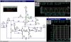
What an earth is R6 doing!!!.
")
hehe, yes I know its bizzare. I have been reading on a lot of tube schematics and the Radiotron Designers Handbook 3 & 4 and have never seen that been used ever, however I thought I would try that in the simulation since I have seen it been used to bias BJTs. I was under the assumption that by using this as a feedback may be it would decrease some distortion at the cost of gain?
You certainly SHOULDN'T have a resistor from anode to gate, the valve is going to seriously melt down!.
Is it because instead of working like a negative feedback it is positive feedback and it would draw too much current? but doesnt the plate resistor limit the current? I am very confused, I know I must be missing something....... Soorry about my newbieness again, since I have not been taught anything on tubes except some minimal reading on my own.....
You're also using an output tetrode as a low signal gain stage, which seems rather bizzare to say the least?.
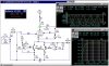
I am actually aiming to use this as a second stage of my amp, with the first stage consisting of a 6SN7 differential amplifier. I can not have the source signal bigger than 1V p-p or I'll get clipping in the simulation, thats why I've only used 1V p-p as the source.
Valves are very tried and tested items, there are many successful circuits about which use them - try studying some, you will see the types of designs that work - you can't just start randomly connecting components together.
That's why I am trying to grasp the basics of biasing but its the gimmics that I am trying to add stops it from working properly, otherwise I have got things to work fine without it. And I would like to find out why my gimmic don't work.......
What sort of amplifier are you wanting to build?, and what valves/tubes do you have available?. Your biggest problems are likely to be transformers - VERY expensive!.
I am actually building this amp as the output of my audio compressor, which I have completed building using the THAT CORP vcas and RMS detector based on their application note.
**broken link removed**
Currently, I am trying to build an amp with 3 stages. The first one consist of 6SN7 differential amp follwed by 2 x 6BA6 remote cutoff pentode differential, then 2 x 6SK7 remote cutoff push-pull but I am having trouble finding a cheap center tap audio transformer..... I am think about getting these.... any thoughts?
**broken link removed**
Since I still haven't got the transformer yet, I've decided to just couple the 6SN7 to 6BA6 and the 6SK7 in series and try to turn this into a stereo output pre amp.(with the gimmics)
Seems a total waste of time, particularly considering you're usually aiming at a constant grid voltage, this is setting a constant cathode current, which will change the grid voltage accordingly.
What gave me the gimmics idea was that I wanted to build a tube VCA, so at first I stuck a fet at the cathode of a triode and trying to change the voltage at the gate to control the gain and it seemed to work OK. I then wanted to use a RMS detector such as the THAT 2252 and feedback the output into the detector to get the DC to control the fet, aiming to turn it into a simple compressr which I have yet to do.
Which lead me to more bizzare fantasy about using transistors at the cathode, since I bought a batch of 100 off ebay and have no use for them at the moment and wanted to find a way to use them up..... I found the voltage controlled current source circuit in my book collection called Converter and Filter Circuit Encyclopedia by Rudolf Graf, so I thought about using it to replace the fet and may be I can rectify the output and invert the DC to the op amp terminal to attenuate the signal. But I want to make sure the circuit is working first before I go and build the rectifying stage for the voltage controlled current source.
BTW, I built my first valve amplifer back in about 1968, it used an EF80 preamp, and a 6BW6 output valve (giving about 3 watts), I used a metal rectifer for the HT supply.
I happen to have a book that I found in a second hand shop a number of years ago, "Quality Amlifiers for A.C. mains", it's dated 1958 - it gives full details of five valve amplifiers!.
Its nice to know I have someone that I can count on whenever I am going off track!