Continue to Site

Welcome to our site!

Electro Tech is an online community (with over 170,000 members) who enjoy talking about and building electronic circuits, projects and gadgets. To participate you need to register. Registration is free. Click here to register now.

  • Welcome to our site! Electro Tech is an online community (with over 170,000 members) who enjoy talking about and building electronic circuits, projects and gadgets. To participate you need to register. Registration is free. Click here to register now.

Transistor tester

Status
Not open for further replies.

Menticol

Active Member
Hello!!!

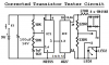
This is my last found. The author states that either LED1 or LED2 will flash if NPN or PNP transistor is working. If both LEDs lit or stay off at the same time, the transistor is wrecked.

Anyway, the schematic was so awfuly drawn that building or correcting it was a nightmare. My contribution was re-drawing it more decently, so you can check it and tell your opinion.

PS: If correct, it would be a nice contribution to Electronic Projects section
 

Attachments

  • transistor.GIF
    transistor.GIF
    7 KB · Views: 2,350
Last edited:
Hello again!

I've found an even simpler design, and I have built it. But the results are a shame!!
The 555 oscilates correctly, but the other section is dead.

Please, what do you think: It's a Defective schematic, or is my fault due defective construction?

PS: Used 2N3904 - 06 for Q1 and Q2.
PS2: I ran out of 220 ohm resistors, so I had to use 300 ohm for R5 and R6 instead
 

Attachments

  • Prob-Trans.PNG
    Prob-Trans.PNG
    16.4 KB · Views: 1,120
Last edited:
Hello again!

I've found an even simpler design, and I have built it. But the results are a shame!!
The 555 oscilates correctly, but the other section is dead.

Please, what do you think: It's a Defective schematic, or is my fault due defective construction?

PS: Used 2N3904 - 06 for Q1 and Q2.
PS2: I ran out of 220 ohm resistors, so I had to use 300 ohm for R5 and R6 instead

hi,
Looking at the circuit, did you attach a transistor to E,B,C...?


EDIT:
The circuit does NOT work in simulation.
Please post the description of what the circuit is supposed to do.
 
Last edited:
Thank you by testing it Eric. The author states that either LED1 or LED2 will flash if the NPN or PNP transistor (connected to the test points) is working. If both LEDs lit or stay off at the same time, the transistor under testing is wrecked.

You are right Mike, the multimeter is a must! This qualifies as a snob, yet still interesting circuit for me.

PS: A more useful device is the ESR meter that I posted some days ago, but no one seems interested on it :(

EDIT: WONDERFUL link Mike! I'm printing that info right now
 
Last edited:
EDIT: WONDERFUL link Mike! I'm printing that info right now

:) Yeah Sam has been posting great info on the net ever since Moby-Dick was a minnow.

Fancy circuits for transistors are not really needed if you learn the power of your most important tool, the multimeter. If you wish to build a more auto tester like one of your circuits, then I see nothing wrong with that. I am sure Eric can help you immensely :)
 
hi menticol,
That design will not work in simulation.!
Is that drawing the original.??

I would suggest we send it to the trash can.:)
 
The first circuit from Electronics-Lab has the pins on the CD4027 IC connected wrong.
I fixed it 2 years ago but the moderator there did not update the project. Here is the correct circuit:
 

Attachments

  • transistor tester.PNG
    transistor tester.PNG
    52.9 KB · Views: 2,242
Here is the Audioguru's correction, applied to the "nice" version of the drawing. No wonder if someone missed the pinout using the other schematic... is confusing!
 

Attachments

  • audioguru_correcition.PNG
    audioguru_correcition.PNG
    15.7 KB · Views: 514
Last edited:
Status
Not open for further replies.

Latest threads

New Articles From Microcontroller Tips

Back
Top