wilbee
New Member
Dear all,
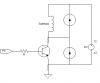
I am constructing a transistor switch which will use a TTL pulse generated from a computer to turn on and off a solenoid valve at the desired frequency.
The solenoid valves has a 2W rating and a requred pd of 24V. I have got a encapsulted 5W supply with a +12V and -12V and 0V outputs. However, when I put on the npn transistor and the emitter linked to the -12V rail and hook the base to the comp output which is either 0 or 5V. the transistor turns on no matter what base volt it is. I uderstand this is happening because there is already a 12V across the base and emitter to turn on the switch.
I tried offsetting this by uisng a differetial op-amp configruation with the inverted computer input (0 or -5v) and -12V as inputs. Therefore the base voltage would be -7 to -12V. However, I failed as the diff op-amp output will never be -12V as the power rail is at +/-12V and a lost is there.
Therefore, are there any solution which will solve this problem?
Thank you very much.
Wil