Continue to Site

Welcome to our site!

Electro Tech is an online community (with over 170,000 members) who enjoy talking about and building electronic circuits, projects and gadgets. To participate you need to register. Registration is free. Click here to register now.

  • Welcome to our site! Electro Tech is an online community (with over 170,000 members) who enjoy talking about and building electronic circuits, projects and gadgets. To participate you need to register. Registration is free. Click here to register now.

Transistor saturation

Status
Not open for further replies.

k7elp60

Active Member
I have lost my thoughts and my notes on the value of resistors to ensure saturation of a transistor. Please correct me where I am wrong. For the 2N3904 if I want the saturation collector current to be 10mA. and the normal β is 100, for a collector current of 10mA. A β of 10 is used, resulting in a base current of 1mA.
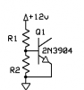
I realize that R2 is not necessary for saturation, but for stability etc it is used. So how do I figure the values of R1 and R2 of the attached schematic for a saturation current of 10mA?
 

Attachments

  • npn saturation.png
    npn saturation.png
    2.7 KB · Views: 155
About 11.2 vdc drop across R1 and 1 mA plus 0.8v/R2.

With reasonable value for R2, R1 of 10k should do.
 
Last edited:
Close enough for gov't work, I guess.

But where do you get 11.2 volts? It may seem a nitpick, but if the typical drop across the transistors's emitter diode is 0.7 volts, then we should see 11.3 volts from the base to V+, corrrect?

So I'd say the top resistor should be

R = E/I = 11.3/0.001 = 11,300Ω

while the bottom one should be

R = E/I = -0.7/0.001 = 700Ω

which all checks out, since the total resistance is

R = E/I = 12/0.001 = 12KΩ

Anyhow, you get the idea. For an actual circuit, you'd use 11K (10K would really be close enough) and 680Ω (820Ω would also be close enough).
 
CZ,
That divider will only put .68 volts at the base, so little or no current will flow thru the base emitter junction.
 
Close enough for gov't work, I guess.

But where do you get 11.2 volts? It may seem a nitpick, but if the typical drop across the transistors's emitter diode is 0.7 volts, then we should see 11.3 volts from the base to V+, corrrect?

So I'd say the top resistor should be

R = E/I = 11.3/0.001 = 11,300Ω

while the bottom one should be

R = E/I = -0.7/0.001 = 700Ω
You do not want 1mA through R2. As ronv noted that leaves no current for the base. Typically you use something like 10kΩ for R2.
 
Aargh. I accept 10 lashes with a wet noodle from both of you!

So how do we set the base resistor? We want 1mA through the base; but how much do we "want" through the base resistor? As little as possible? Why do we need a base resistor at all? (OK, someone up there said something about "for stability", so I guess I'll accept that on faith.)

Should we just arbitrarily say 1mA through the resistor (equal split of current through the resistor and emitter diode)? Of course, then we have >1mA through the entire thing, which puts us back at square one.

My head hurts ...
 
Typically R2 is used to stabilize the bias when the transistor is used as a linear amplifier.

For switching circuits it's there to absorb any high temperature base leakage current and perhaps, help remove some of the base carriers to reduce the turn-off time in high speed applications. For typical hobbyist applications you usually don't even need R2 for switching applications.
 
You really need to know how, and if, the transistor is being turned on via a previous circuit, as it would certainly not take 1mA to "saturate" the transistor as it is not being saturated.
If the transistor has a gain of 100, it will have this gain at 10mA and it will only take 0.1mA to provide (produce) a collector current of 10mA.
The base biasing can be a simple base resistor or a voltage divider.
If you want to consume the least current, use a simple base resistor. This will also allow the transistor to operate with a wider rail voltage.
These things have to be decided first before working out the resistor-value(s) as the circuit, as is, is a "do-nothing" circuit.
 
You really need to know how, and if, the transistor is being turned on via a previous circuit, as it would certainly not take 1mA to "saturate" the transistor as it is not being saturated.
If the transistor has a gain of 100, it will have this gain at 10mA and it will only take 0.1mA to provide (produce) a collector current of 10mA.
0.1mA will produce a collector current of 10mA but it will not likely cause the transistor to "saturate" (fully turn on with lowest collector-emitter voltage). The transistor gain (beta or Hfe) value is for small signal linear applications, not switching. For reliable saturated switching of any bipolar transistor you should use a forced beta of 10 (or no more than 20 if you need to minimize base current).
 
This is totally unrelated to the topic: "The transistor gain (beta or Hfe) value is for small signal linear applications, not switching." And it's rubbish.
 
Saturation Vbe will be a bit higher, that is why I used 0.8 volts.

The Rbe resistor only needs to be low enough to hold the transistor in cutoff when drive is released. 15k should be fine. That would steal about 50 uA from the 1 ma base drive.

Vce(sat) @ Ic=10mA = 0.2 volts (typ)
Vbe(sat) @ 1 mA Ib = 0.85 vdc (typ)
Forced beta = Ic/Ib = 10mA/1mA = 10
 
Last edited:
"Rbe resistor" is determined by the value of the resistor between base and supply. How did you work out 50uA?
 
"Rbe resistor" is determined by the value of the resistor between base and supply. How did you work out 50uA?

Not really, just figured value where 5% of base current was stolen. With 1 mA of base drive, I allowed 50 uA to leak off through Rbe.
 
"Rbe resistor" is determined by the value of the resistor between base and supply because you don't need 1mA base current to deliver 10mA collector current. Although we haven't been given the full details of the circuit, the "do-nothing" circuit will operate at a much lower base current. It depends if you want to design the circuit for battery operation or "don't care" operation.
 
If R1 is 1.2K. R2 can be arbitrarily any high value like 1meg. Then the base current is 1mA.

edit: 12K not 1.2K
 
Last edited:
you don't need 1mA base current to deliver 10mA collector current.
We are not talking about an amplifier transistor that has plenty of collector to emitter voltage so beta is used. Instead we are talking about a saturated switch where the max saturation voltage is spec'd when the base current is 1/10th the collector current.
 
I can see by this back-and-forth among the "experts" here that this is far from settled science.

I like it. You can really see from this why they call it the "art of electronics".

Keep going, please.
 
""If R1 is 1.2K. R2 can be arbitrarily any high value like 1meg. Then the base current is 1mA."
R1 has to be higher than 10k.
 
Status
Not open for further replies.

Latest threads

New Articles From Microcontroller Tips

Back
Top