Continue to Site

Welcome to our site!

Electro Tech is an online community (with over 170,000 members) who enjoy talking about and building electronic circuits, projects and gadgets. To participate you need to register. Registration is free. Click here to register now.

  • Welcome to our site! Electro Tech is an online community (with over 170,000 members) who enjoy talking about and building electronic circuits, projects and gadgets. To participate you need to register. Registration is free. Click here to register now.

Transistor Question

Status
Not open for further replies.

krich

New Member
I'm fairly inexperienced with electronics in general, but I've learned quite a bit over the last many months of self instruction (and some really good help from forums like these). I have one question on transistors whose answer has eluded my normally excellent googling skills, so I figure I would just throw out the question on this forum in hopes of getting an answer.

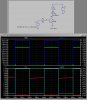
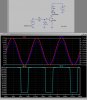
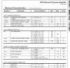
With a regular 2n3904 transistor, what happens if my base voltage is significantly higher than the voltage that I am switching on the Collector/Emitter? 12V on the base side, 5V on the collector/emitter side.

I've looked at a few javascript simulators I've found online and it says my Ve=11.3V (allowing for the forward voltage drop b to e.). Is this correct? I was worried that the simulators might not handle this "reverse scenario" correctly.

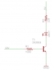
Here's an example scenario:

I have a garage opener button in my garage just outside the back door. It operates on 12V. Close the circuit by mashing the button and the door opens/stops/closes.

I would like to hook up a MCU (Atmel) running at 5V to the button to detect when the button is pressed. All the inputs are max 5V, so I was thinking of using a transistor as a switch. But I worry I'll send ~12V to my MCU inputs, which is grossly out of spec and generally a bad thing.

So, is a transistor just the wrong part for the job if my base voltage is higher? I really want to understand when I can and when I can't use a transistor for such things. What about PNP?

I know there are other solutions like a relay or a solid state relay/optoisolator, which would protect the 5V side from the 12V side. This is more about understanding how a transistor works than figuring out this particular example. I've run into this situation on more than one occasion.
 
Draw a circuit. It is hard to picture how you are using the transistor. Dont forget that in most switching applications where transistors are used, there is a series current-limiting resistance in the base circuit. Sometimes this takes the form of a series resistor, and sometimes a resistive divider consisting of two resistors, one to supply, the other to supply return...
 
Okay, I was worried my example was going to derail folks from the essential question. Here's a schematic to ponder. Notice that 12V at the base is driving a 5V load. Will this work? Why or why not? What are the voltages at the collector, emitter, and why?
 

Attachments

  • tq.PNG
    tq.PNG
    9.6 KB · Views: 234
With some transistors you may get some of the base voltage leaking through from the base to the collector. This may or may not be a problem depending on the circuit it is connected to. In your example circuit your base resistor
is way too small I think 100 k would be a better value, that way the 12 v.
would have less effect on the circuit.
 
Thanks Brevor. Do you think the LED will light?

I agree with your assessment on the base resisotr. I didn't do any calculations to make sure my resistor values were right because this is a purely hypothetical circuit diagram.
 
Do you think the LED will light?

Probably, Also with the circuit you show you should not have any problems with the higher input voltage because with the emitter grounded the base will never go above about .7 v. My warning about voltage feeding through to the collector would only happen if you had a resistor in the emitter circuit.
 
Okay, I was worried my example was going to derail folks from the essential question. Here's a schematic to ponder. Notice that 12V at the base is driving a 5V load. Will this work? Why or why not? What are the voltages at the collector, emitter, and why?

Think of it like this: the transistor is used as a switch. Its collector current (same as the LED current) is determined by the 220Ω resistor by Ohms Law Ic=E/R=(5-Vled-Vcsat)/220. The forward drop across the LED is ≈2V. The saturated collector voltage Vcsat of the NPN when is turned on is ≈0.2V, so I=(5-2-0.2)/220 ≈ 13mA.

In order to make the collector current of the NPN 13mA, it would take a base current Ib of at least Ic/β where β is the min. current gain of the NPN. Lets say that your NPN has a β of 100, so Ib=13mA/100 = 130uA.

The base current Ib = (12-Vbe)/Rb. Vbe of a turned on transistor is ≈ 0.7V, so substituting and rearranging gives Rb = 11.3/130e-6 = 86K. I would round that down to a commonly available value, like 47K...

So you see, the base resistor only needs to supply sufficient base current to turn on the transistor. The current gain of the transistor "amplifies" this current to switch a much higher current at its collector.

Look at the attached sim.
 

Attachments

  • NPNswitch.jpg
    NPNswitch.jpg
    229.5 KB · Views: 186
In order to make the collector current of the NPN 13mA, it would take a base current Ib of at least Ic/β where β is the min. current gain of the NPN. Lets say that your NPN has a β of 100, so Ib=13mA/100 = 130uA.

The base current Ib = (12-Vbe)/Rb. Vbe of a turned on transistor is ≈ 0.7V, so substituting and rearranging gives Rb = 11.3/130e-6 = 86K. I would round that down to a commonly available value, like 47K...
When using a transistor for switching it is generally recommended to use a β no greater than 10 to insure that the transistor is well turned on with minimum collector-emitter voltage drop. (The higher β value is used when the transistor is being used as a linear amp.)

The base current would then be 1.3mA and the base resistor would be 11.3/1.3e-3 = 8.6kΩ.

Gee Carl, you must have started when most transistors had a β of 20 :D

Nowadays, you are had pressed to find a transistor with a β less than several hundred.

Also, most folks usually put a resistor between base to emitter to pull charge out of the base-emitter junction, and to guarantee turn-off at high temperatures, so the input resistor is chosen to supply base current + the shunt resistor current.
 
Place Rbe please.
Rb = 8K2, Rbe = 1K ;for slowspeed 12V input,
so the transistor turned in saturation on-state and turned off well through 1K Rbe.
 
Last edited:
The ratio of R3 to R2 determines at what minimum input voltage the LED turns on. Your values didn't work (the NPN never fully turned on).

Look at my values:
 

Attachments

  • NPNswitch1.jpg
    NPNswitch1.jpg
    233.5 KB · Views: 171
So you see, the base resistor only needs to supply sufficient base current to turn on the transistor. The current gain of the transistor "amplifies" this current to switch a much higher current at its collector.

Look at the attached sim.

Thanks MikeMl for taking the time to simulate this for me. Is that a 12V source on the base (pulsed)?

So, from all the feedback on this, I needn't worry about 12V getting to my MCU and toasting a pin. I think most of my pins have clamping diodes, but still...

I noticed a second base resistor in the second simulation you did. Is that resistor placed as a "pull down" resistor to fully shut off the transistor? It also looks like it creates a potential divider, which will need to be taken into account when calculating the values. Am I on the right track?
 
...
I noticed a second base resistor in the second simulation you did. Is that resistor placed as a "pull down" resistor to fully shut off the transistor? It also looks like it creates a potential divider, which will need to be taken into account when calculating the values. Am I on the right track?

Right on.

Since you said "slowly rising", I modeled the input as a sine wave which goes from 0V to 12V. See the red trace V(In) in the upper plot pane. Note that the transistor switches when the input crosses about 3V. If you want a different trip point, you can play with the R2/R3 ratio.
 
Gee Carl, you must have started when most transistors had a β of 20 :D
HFE or beta is not used when a transistor is saturated.
Simply look at the datasheet of a modern transistor like a 2N3904:
1) With a collector to emitter voltage of 1V or more and a collector current of 10mA its minimum base current is one 100th.
2) With the transistor saturated with a collector to emitter voltage of 0.2V or less and a collector current of 10mA its minimum base current is one 10th.
 
Why calculate it out? There's a traditional rule that the base current should be 10 times the collector emitter current to act as a switch, special cases aside, go by that general rule and you'll skip about 2 years of math.
 
Last edited:
Some transistors like the BC547 have their saturation voltage loss rated when the base current is 1/20th of the collector current.
 
It's very nice when it's specifically stated like that. Let you relax design requirements with assurance.

I'm not an expert mind you, but everywhere I have read 1/10th is the rule of thumb, basically what you have to do is under all thermal and voltage conditions guarantee that the transistor will never come out of saturation and go into it's linear region or you'll get thermal runaway and transistor self destruction. I've heard little of safe operating area conditions but don't know much about them or how they're calculated.
 
Last edited:
HFE or beta is not used when a transistor is saturated.
Simply look at the datasheet of a modern transistor like a 2N3904:
1) With a collector to emitter voltage of 1V or more and a collector current of 10mA its minimum base current is one 100th.
...

Excuse me, but the OP's collector current is only 13mA, and he is dropping about 3V across the current limiting resistor, so it doesn't matter if he drops an addional 0.8V or so across Vce. Look at the attachment from Fairchild. They are happy to rate the β at 100 to 300 near that Ic. Using a base current which gets the Vce to less than 1V is more than sufficient to turn on the LED.

There is no separate section on Fairchild's Data Sheet which differentiates between using the 2N3904 as an amplifier or as a switch, only how low can you get Vce! The test circuit where Ib=1ma is only to determine minimum switching speed, which is of no consequence to the OP who is switching an LED.

At Ic=13mA, there is no requirement that the saturation voltage of the transistor be at an absolute minimum. A base current twice that determined by βmin is more than good enough...
 

Attachments

  • 2n3904ss.jpg
    2n3904ss.jpg
    172.6 KB · Views: 161
Last edited:
Status
Not open for further replies.

Latest threads

New Articles From Microcontroller Tips

Back
Top