hello,
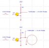
as shown on the figure below, in the first case when i set a 0-5V pulse on input of a transistor, i get a 0-24V pulse on the output, as expected...
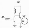
but in the second case in the figure, when a attach a load, the voltage drops to 4V on the output... what is the problem??? how can i fix that?
how can i fix it?
thanks in advance
as shown on the figure below, in the first case when i set a 0-5V pulse on input of a transistor, i get a 0-24V pulse on the output, as expected...
but in the second case in the figure, when a attach a load, the voltage drops to 4V on the output... what is the problem??? how can i fix that?
how can i fix it?
thanks in advance