Continue to Site

Welcome to our site!

Electro Tech is an online community (with over 170,000 members) who enjoy talking about and building electronic circuits, projects and gadgets. To participate you need to register. Registration is free. Click here to register now.

  • Welcome to our site! Electro Tech is an online community (with over 170,000 members) who enjoy talking about and building electronic circuits, projects and gadgets. To participate you need to register. Registration is free. Click here to register now.

transistor pair and capacitor

Status
Not open for further replies.

kunmycharles

New Member
pls can someone please give me a technical explanation about how this circuit works
 

Attachments

  • scan0002.jpg
    scan0002.jpg
    200.2 KB · Views: 1,652
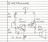
Originally a very early 1960's circuit, when transistors used to cost over a dollar each (then), smart designers were the ones who's circuits had less parts. This came from a time when oscillators normally used a unijunction transistor, so this was a much cheaper way of getting this 'UJT'.

Techy explanation: When the PNP transistor turns ON, it discharges the capacitor and it turns itself off, so the cycle repeats again.


Now the practical explanation which is much more fun!

The plumber was called in to fix a leak, he replaced the pipes and found 'some other work that needs doing' and did that too and his bank manager was happy that week. Later in the week, all the water was shut off in premises, and the central heating drained too, all he to do was wait until the last tank has drained down, then eliminate all the pipework in the heating system too. Still no joy, so now it must be a leak in the roof, maybe a collected pool of water somewhere, so the builder's called in to estimate the cost of replacing the suspended ceiling which has to be removed when the roof is redone. While measuring up, his mate, holding the tape measure, notices a wire and a battery inside a ventilation duct.

It was one of these bloody metronomes going blip every few seconds for the last 3 weeks!!! :D
 
Last edited:
It's from a Forest Mims book; this circuit is normally repeated a couple of times in each of his books, with different component values and no explanation of how it works.
 
I think this circuit might date back before Forest Mimms, to the 1950's, when transistors looked like these.

**broken link removed**

scan0002-jpg.32057
 
Last edited:
It's a beautiful oscillator circuit, energy efficient and reliably starting. And 2N2222 and 2902 are hardly 1950's.

The metronome timed period is caused by R1+R2 into C1, when C1 charges to 0.6v Q1 starts to turn on, turning on Q2, its collector voltage risies rapidly which turns on Q1 even harder via positive feedback from C1. The speaker voltage rises close to 9v rail voltage, then when C1 has delivered all its charge into Q1's base there is nothing to keep Q1 on, so everything starts to turn off, C1 again positive feedback making the turnoff quick. Both turn on and off would be very fast.

Timed period is R1+R2 to C1, speaker hi period is very short and fixed, set by psu voltage and C1 value.

The only downside I can see is that the metronome period is very influenced by psu voltage and it will get slower as the 9v battery voltage drops.
 
Status
Not open for further replies.

Latest threads

New Articles From Microcontroller Tips

Back
Top