Follow along with the video below to see how to install our site as a web app on your home screen.
Note: This feature may not be available in some browsers.
I read the graph as Vce(sat)~200mV at Ic=2A. Notice the graph says this is with Ic/Ib=10 (Ib~175mA). I would recommend using this drive ratio, because beta is lower in saturation than it is with Vce=4V, which is where the beta numbers you quoted are specified.eblc1388 said:NPN transistors are turn ON via current going into the base pin.
First one have to determine the load current. For a lamp of 21W at nominal 12V supply, the current is 21W/12V=1.75A. However, we should allow for extra margins so I would say about 2A.
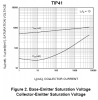
If you than look at the datasheet graph on page 2 "DC Current Gain", it gives a current gain at this particular current to be 40. Again we allow for some margins so I would say it is about 30. Thus for a collector current of 2A, the base current will be roughly 2A/Gain = 2A/30 = 67mA.
If this is an industrial application, I would even lower the DC gain to 15 according to the figure quoted by page1 of the datasheet(Hfe Min 15 at 3A). This ensure the TIP41C will will be fully ON no matter what.
EDIT: I would look at using a MOSFET instead of a bipolar transistor.
Thus in your case you need to pass a current of 67mA into the base pin to result in a collector current flow of 2A. At this current, the Vbe(sat) is about 1V and you can work out the resistor value say from a 5V drive. Base resistor = (5 - Vbe(sat) ) / 67mA = 60 ohm.
Of course in real life the lamp current will be less than 21W/12V because at 2A, the saturation voltage of the TIP41C is about 2V thus only about 10V is available to light up your lamp. Your TIP41C is dissipating 3~4W of heat so it will definitely need a heatsink.
Hopes this help.
I think he was looking at the possibility of surge current limiting as a good thing. With 175mA base drive, you should get some limiting.audioguru said:Hi L. Chung,
The hFE of a transistor is used when it has 4V across it as a linear amplifier. When the transistor is saturated then it needs a much higher base current.
The base current is shown to be 1/10th the collector current for the spec'd saturation voltage. Then the base current should be 175mA.
Hi K7,
The current gain of a transistor is a range. Some are good and others are not very good. If you design the circuit so there is enough base current for all transistors like I do then the sensitive ones will conduct much more than the weaker ones and not limit the surge current.
Roff said:I think he was looking at the possibility of surge current limiting as a good thing. With 175mA base drive, you should get some limiting.
EDIT: I would look at using a MOSFET instead of a bipolar transistor.
They're not, at least on the datasheet that Fingaz posted.eblc1388 said:Good catch, Roff. Not aware that Y-axis was with different scale between Vce(sat) and Vbe(sat).
Roff said:They're not, at least on the datasheet that Fingaz posted.
I'm taking medication for that right now.eblc1388 said:No. they are of the same scale. I don't know why I have said that.
I must have contacted the "foot in mouth" virus.
Yes you are right and if one designs the circuit for the minimum current gain then any transistor with higher gain will also work. I mentioned surge current as it could be possible that the surge current could be greater than the maximum collector current of the transistor.audioguru said:Hi L. Chung,
Hi K7,
The current gain of a transistor is a range. Some are good and others are not very good. If you design the circuit so there is enough base current for all transistors like I do then the sensitive ones will conduct much more than the weaker ones and not limit the surge current.