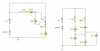
Hi i have some questions about the two different configurations of transistor in the pic.
I have the following figures for a 200 hfe transistor which was run in a simulator.
[A]
ve = 7.3v
vc = 8v
vb = 8v
Ib = .06ma
Ic = 13.2ma
Ie = 13.2ma
ve = 0.3v
vc = 0.4v
vb = 0.8v
Ib = 7.32ma
Ic = 14ma
Ie = 27ma
How does the sim calculate the following:
How is the vc calculated in both examples ?
How is the vb calculated in both examples
How is the ve calculated in both examples ?
How do i calculate the vcc voltage with these figures ?
How do i calculate the emitter or collector resistor load ?
Thanks