Continue to Site

Welcome to our site!

Electro Tech is an online community (with over 170,000 members) who enjoy talking about and building electronic circuits, projects and gadgets. To participate you need to register. Registration is free. Click here to register now.

  • Welcome to our site! Electro Tech is an online community (with over 170,000 members) who enjoy talking about and building electronic circuits, projects and gadgets. To participate you need to register. Registration is free. Click here to register now.

Transistor Biasing

Status
Not open for further replies.
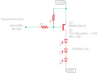
I need help calculating the correct resistor values in the circuit shown. Basically the circuit is connected to a micro and is used to drive a 50mA load (LEDs) that run on 12V. When the micro output is high the LEDs are off and when the micro output is low the LEDs are on (0 to 5v signal). With a bit of experimenting I found values for R1 and R2 of 390 ohms and 4.7K respectively make the circuit work. My question is how do I calculate that without doing experimental guesswork? I tried watching videos on transistor biasing but I can't get a grip on it, most likely because of the multiple voltage sources involved.

Any help is appreciated.
 

Attachments

  • Trans.png
    Trans.png
    4.6 KB · Views: 153
This circuit is almost impossible to make work.
With out R1, Q1 will be on at 0V and 5V.
You can try to make a voltage divider out of R1, R2. With "5V=off" the voltage on Q1 Base-Emitter must be less than 0.65V and at "0V=on" the B-E voltage must be more than 0.7. If the temperature of Q1 changes the turn on voltage will change. If 12V is a little off then ...... not working.

1594515502501.png

This circuit is pretty forgiving, if the 12V is off or if the temperature is different.
1594516119517.png

As long as I am here; It is not a good idea to put 12V across LEDs. There should be a resistor or something to limit the LED current. LEDs run on current not voltage.
 
You want math. I forgot.
50mA Q1 Collector.
Gain of 100. That gain is high if you want the transistor to turn on good. So I am going to try 1mA, gain of 50.
Q2 Emitter resistor: Base at 5V, About 4V across the resistor so that is 1mA.
Q2 Collector current is about 1mA.
R1=0 ohms or (no resistor)
1mA is pulled from Q1 Base.
R1 will steal away a little current. I just picked 4K because we already have on in use.
1594516532153.png
 
First, check the datasheet of your microcontroller, many (most) don't like current to flow into the pins when the pin is supposed to be "high". So, in general, this PNP configuration is a terrible idea.

the BEST way to switch the 12VDC with a microcontroller and a PNP is to set the micro pin to OUTPUT LOW to turn ON the LEDs. Then, set the micro pin to INPUT and no current will flow from the PNP base to turn the LEDs off.

If I understand what you're suggesting correctly?, that's completely untrue - UNLESS the PNP supply rail is only the same as the micro (5V). With the 12V shown the PNP will never be able to turn OFF at all - as the micro pin will never rise above it's Vdd voltage. Even the few pins that might be open-collector don't usually allow the pin to rise above Vdd either. The majority of micros have protection diodes on the pins, which link to Vdd and Vss, preventing your idea.

The suggestion in post #2 is the standard way of doing it, and turns the LED's ON when the input goes high (which is the sensible way to do it) - however, a series resistor for the LED's is essential, and could be added in the PNP emitter, to give a crude 'constant current' type effect.

Yup, your right. I was trying to get this very bad circuit to work but, there is a reason nobody does it the OP's way.
 
Since the transistor base current is too low for it to saturate, does the transistor glow brighter and hotter than the LEDs?
 
Is there any reason to use a PNP? The circuit would work better with an NPN.

Mike.
 
Is there any reason to use a PNP? The circuit would work better with an NPN.

Mike.

I presume you mean low side switching rather than high side?.

However, I'm dubious about the use of the word 'better' - the advantage of the high side switch is that you can provide more current for the base of the switch, in order to better saturate it. Assuming low side switching is acceptable, and the current isn't too high, then a single NPN as alow side switch is certainly simpler.

The basic idea for both is shown in my tutorial 'extras':
 
Status
Not open for further replies.

New Articles From Microcontroller Tips

Back
Top