Continue to Site

Welcome to our site!

Electro Tech is an online community (with over 170,000 members) who enjoy talking about and building electronic circuits, projects and gadgets. To participate you need to register. Registration is free. Click here to register now.

  • Welcome to our site! Electro Tech is an online community (with over 170,000 members) who enjoy talking about and building electronic circuits, projects and gadgets. To participate you need to register. Registration is free. Click here to register now.

transistor bias / saturation

Status
Not open for further replies.

MrDEB

Well-Known Member
need a low pulse to trigger a 555 timer.
using a 2n2222 transistor to ground
is this correct.
I used a simulation program and it looks good but ??
I have a feeling I need a capacitor??
 

Attachments

  • Capture2-22-2009-2.14.01 PM.jpg
    Capture2-22-2009-2.14.01 PM.jpg
    105.8 KB · Views: 205
Your circuit will work if the switch is pressed for a short period of time.
If the switch is kept pressed, the output of the 555 will remain HIGH.
 
You will get a number of short pulses at pin 2 due to the switch contacts bouncing for a few milliseconds.
 
These pulses don't matter as the 555 just recognises the first pulse. Or more accurately, the first time the voltage level is below 1/3 of rail voltage.

You do not need the transistor. Except the transistor is inverting the signal.

You will need to place the switch between pin 2 and ground, while keeping the pull-up resistor.
 
Last edited:
Is the switch totally isolated or does one side go to the 12v line.

Can the position of switch be altered.
 
the input is 12v

a high signal but the 555 needs a low signal.
with a high signal input at the base the transistor grounds the # 2 pin thus creating a low signal and the 555 progress to do its thing.
 
Why can't you use a pullup resistor to make pin 2 high then use the switch to ground it and trigger it?
 
the switch is just a represention

of the 12v input that triggers the 555.
there is a switch but its elsewhere.
I just included it to show that the 12v is not always present.
 
as long as the transistor switch works

and it produces a low on pin 2 then I am happy.
I get lost figuring transistor bias etc.
using TINA and **broken link removed** to figure transistor switching.
 
different circuit for correct values??

Vcc=14v
Rl = 400ohm
2n2222 transistor
base resistor = 8K
caculated voltage using TINA at collector = 113.73mv
34ma Vcc to Rl
Base current = 1.65ma @ 795mv
I am assuming that the collector voltage is near ground so transistor is saturated??
 
pic of cal measurments

the 14ma is what was measured by someone else.
I changed the resistor load and base resistor with not much change.
I assume that if the base current is within the output of the ic and the collector voltage is near ground .7v or there abouts the the transistor is saturated??
 

Attachments

  • Capture2-24-2009-11.33.15 AM.jpg
    Capture2-24-2009-11.33.15 AM.jpg
    113.2 KB · Views: 144
You have got to answer our questions if you want us to help you, rather than going down your own path.

We asked: Is the switch connected to anything?

This is the first question we need answered.
 
MrDeb,

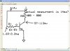
In your second circuit, I believe that your power supply is not keeping up with demands. The 0.113V at the collector suggests an "effective resistance" for the transistor of 282 milliOhms, thus the expected current when 14V are applied to 400 Ohms is 35mA. The fact that your friend measures 14mA suggests that your power supply is not keeping up with demands.
The low "effective resistance" suggests that your transistor is indeed saturated. The measured base current of 1.65 mA when applied to a transistor with a beta of say 100 would give you a collector current of 165 mA. The 400 Ohm resistor is preventing you from seeing that.

P.S. - Experts, if I am incorrect in my analysis of the second posted circuit, please correct me.

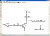
P.P.S. - As far as the first circuit is concerned, there seems to be little reason for the transistor as many have already noted.
 
If Rl is 400 ohms and the supply is 14V then the current when the transistor is turned on is (14V - 0.13V)/400 ohms= 43.7mA.
The base voltage is about 0.65V so the base current in the 8k resistor is (14V - 0.65V/8k ohms= 1.67mA. Some of these transistors needs a base current of 4.37mA to saturate.
 
You are all running around in the wrong circle.

The interface to the 555 requires a high impedance stage and this cannot be worked out until it is known if the switch can be positioned HIGH or LOW.
 
Status
Not open for further replies.

Latest threads

Back
Top