Electro Tech is an online community (with over 170,000 members) who enjoy talking about and building electronic circuits, projects and gadgets. To participate you need to register. Registration is free. Click here to register now.
Welcome to our site! Electro Tech is an online community (with over 170,000 members) who enjoy talking about and building electronic circuits, projects and gadgets. To participate you need to register. Registration is free. Click here to register now.
Hi guys I need a small PWM generator circuit to control brightness of two LEDs. well I'm looking for a transistor based circuit.any ideas? (i want to make it smaller thats why i didnt choose 555 timer)
thanks
anyway what is the more efficient way of brightness control? using pwm or using constant current source?
i guess its PWM as constant current source burn energy through a resistor
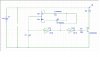
See the circuit with the opamp. Replace the resistor and zener in series with a potentiometer. That will make it possible to control the voltage over emitter resistors and therefore also the current through collector.
See the circuit with the opamp. Replace the resistor and zener in series with a potentiometer. That will make it possible to control the voltage over emitter resistors and therefore also the current through collector.
The diodes used in my circuit are not critical, the 1N4148 will do.
The circuit you posted won't be any better than an LED with a resistor connected in series because the transistor is in series with the LOAD, not the LED. Read the Wikipedia article and you'll see why.
The diodes used in my circuit are not critical, the 1N4148 will do.
The circuit you posted won't be any better than an LED with a resistor connected in series because the transistor is in series with the LOAD, not the LED. Read the Wikipedia article and you'll see why.
@hero999
i simulated circuit i posted and circuit you posted.
both are working
but i cant control led (load) voltage using the pot. how much i adjust the pot voltage drop in led remain constant
current varies as pot changes.but it does not change voltage drop on LED.I assume as pot changes voltage drop on LEDs should change becase as pot change Vb changes therefore Ve should change making voltage drop on LEDs to vary
You can use a 30k pot (I've never seen such a beast) but you need to increase R3 to 22k if you want to use it.
I wouldn't suggest a higher value, I'd recommend going lower, do you have a 2k or 1k resistor?
You can use 30k if you like but it's bit high because of the loading created by the base current.
The regulator works because the base-emitter voltage is roughly equal to 0.7V and the diodes drop 0.7V each (1.4V in total).
The base voltage of Tr1 is varied between just under 0.59V to 1.4V as the pot is adjusted, the emitter voltage will always be 0.7V below the base so will vary between 0V and 0.7V.
Because the voltage across R2 is kept constant Ohm's law that the current through it remains constant so the current will vary between 0/33 and 0.7/33 or 0 to 21mA.
This site uses cookies to help personalise content, tailor your experience and to keep you logged in if you register.
By continuing to use this site, you are consenting to our use of cookies.

")